Search
Mechanical and Fluid Systems
3D-Printed Injector for Cryogenic Fluid Management
NASA's TVS Augmented Injector includes an internal heat exchanger, a fluid injector spray head, and an external surface condensation heat exchanger - all combined with multiple intertwined flow paths containing liquid, two-phase, and gaseous working fluid. The TVS provides a source of coolant to the injector, which chills the incoming fluid flow. This cooled flow promotes condensation of the tank ullage dropping pressure and maintains incoming fluid flow. The system eliminates the potential for a stalled fill condition and reduces tank pressure during cryogenic fluid transfer. During fill operations, the tank vent can be closed early in the process before fluid is introduced, and, in some cases, the tank vent may not even need to be opened. Furthermore, the TVS Augmented Injector can remove sufficient thermal energy to reach a 100% liquid level in the receiver tank. A cryo-cooler can be used in place the TVS flow circuit for a zero-loss system. The TVS Augmented Injector couples internal fluid flow cooling and external surface ullage gas condensation into a single, compact package that can be mounted to small tank flanges for minimal impact insertion into any vessel. The injector is printed as one part using additive manufacturing, resulting in part count reduction, improved reproducibility, shorter lead times, and reduced cost compared to conventional approaches.
The injector may be of particular interest in applications where cryogenic fluid is expensive, fluid loss through vents is problematic, and/or achieving high filling levels would be helpful. The injector can benefit typical cryogenic fluid transfer between containers or, alternatively, can serve as a tank pressure control device for long-term storage using a fluid recirculation system that pumps fluid through the injector and sprays cooled liquid back into the tank. Additionally, where ISRU processes are employed, the injector can be used to liquefy incoming propellant streams.
Power Generation and Storage

CryoQuad
Traditional cryogenic cooling methods, such as pulse-tube and reverse Brayton cryocoolers, are constrained by moving parts, high mass, and limited cooling capacity. Their mechanical complexity increases maintenance needs and reduces reliability, while their bulk adds significant weight penalties to mobile platforms. Although these systems can achieve kilowatt-scale cooling, they struggle to maintain stable, efficient performance under the continuous, high thermal loads required for megawatt-scale superconducting propulsion. The CryoQuad was developed specifically to address these shortcomings, delivering a lighter, more reliable, and higher-capacity solution tailored for superconducting electric propulsion systems.
The novel design utilizes four thermoacoustic Stirling heat engines arranged a quarter wavelength apart in a quad loop configuration. This configuration – wherein each engine has high-power acoustic energy pulled off via power pulse-tube coolers – allows for rapid acoustic wave amplification without moving parts (e.g., pistons, turbines, pumps) or electricity. Importantly, the innovative design eliminates the need for large linear piston generators and large recuperator heat exchangers – two features common in megawatt-scale cryocooling pressure systems today – significantly reducing the overall system mass and complexity. While designed for use with liquid Helium, CryoQuad can utilize a variety of fluids depending on the required cryogenic temperatures.
CryoQuad has the potential to be used in superconducting electric aircraft, other advanced propulsion systems, in-space cryogenic fluid management, cryosurgical cancer treatment probes, MRI systems, cryogenic cooling and packaging systems for superconducting electronics, space fuel depots, and other power applications. CryoQuad is available for patent licensing.
Instrumentation
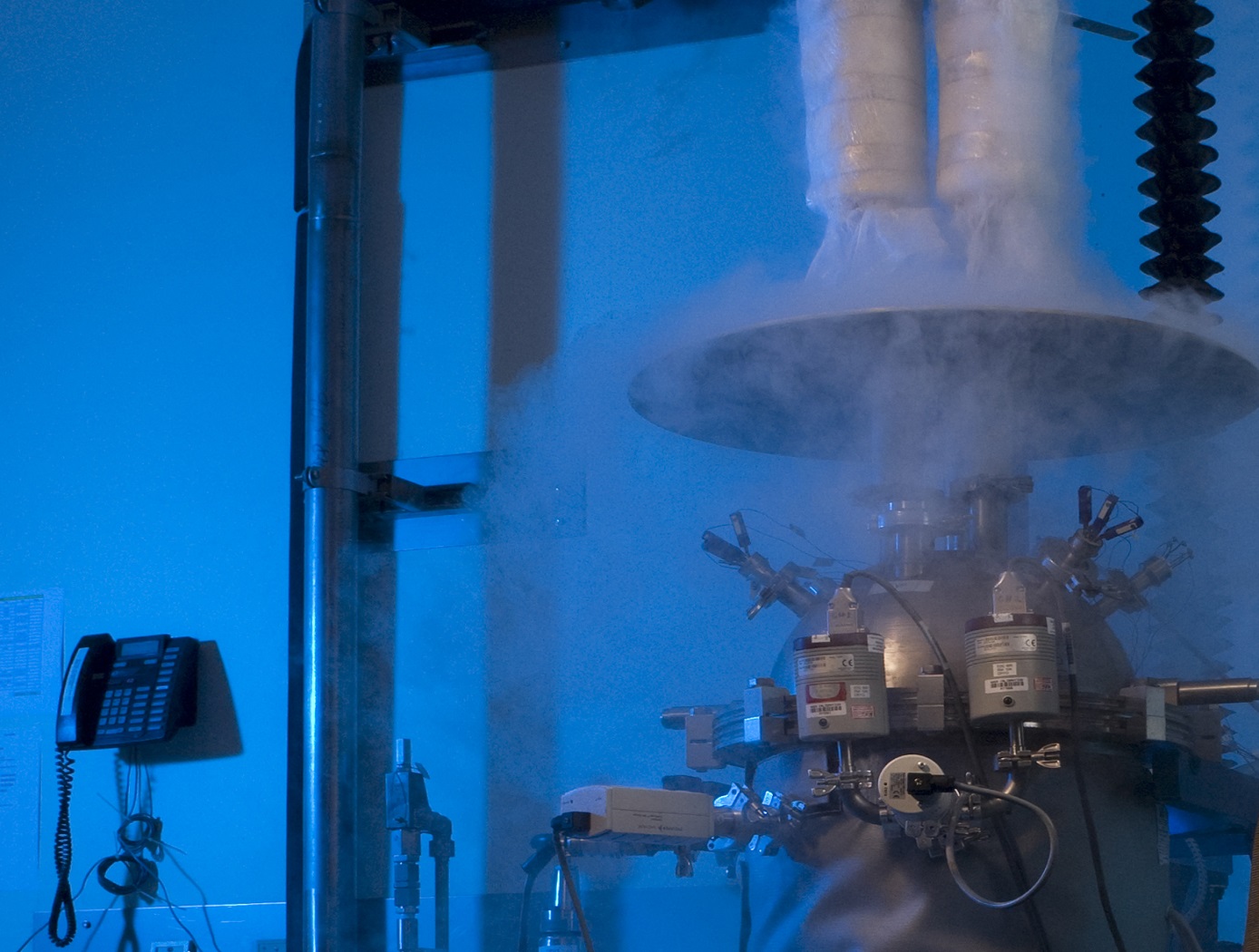
Cryostat-100
Cryostat-100 combines the best features of previous cryostats developed by NASA, while offering new features and conveniences. This unit can readily handle the full range of cryogenic-vacuum conditions over several orders of magnitude of heat flux. Guide rings, handling tools, and other design items make insulation change-out and test measurement verification highly reliable and efficient to operate. The new apparatus requires less ancillary equipment (it is not connected to storage tank, phase separator, subcooler, etc.) to operate properly. It is top-loading, which makes disassembly, change-out, and instrumentation hook-up much faster. The thermal stability is improved because of internal vapor plates, a single-tube system of filling and venting, bellows feed-throughs, Kevlar thread suspensions, and heavy-wall stainless-steel construction.
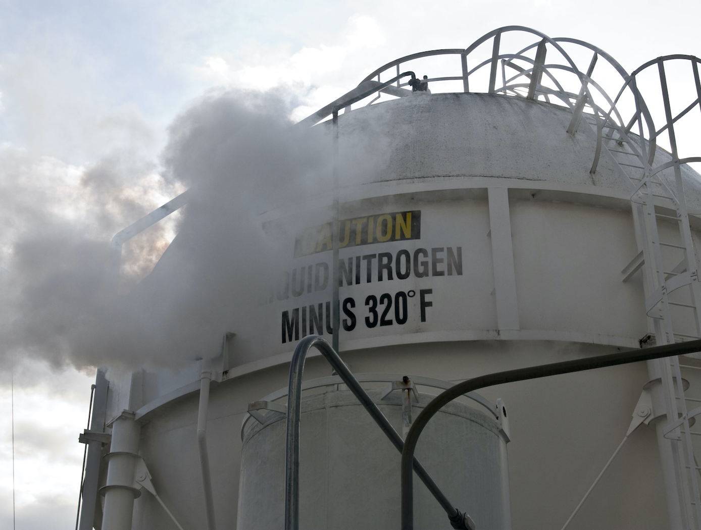
The cold mass of Cryostat-100 is 1m long, with a diameter of 168 mm. The test articles can therefore be of a corresponding length and diameter, with a nominal thickness of 25.4 mm. Shorter lengths are acceptable, and thicknesses may be from 0 mm to 50 mm. Tests are conducted from ambient pressure (760 torr) to high vacuum (below 110-4 torr) and at any vacuum pressure increment between these two extremes. The residual gas (and purge gas) is typically nitrogen but can be any purge gas, such as helium, argon, or carbon dioxide.
Typically, eight cold vacuum pressures are performed for each test series. The warm boundary temperature is approximately 293 K, and the cold boundary temperature is approximately 78 K. The delta temperature for the cryogenic testing is therefore approximately 215 K. A unique lift mechanism provides for change-out of the insulation test specimens. It also provides for maintenance and other operations in the most effective and time-efficient ways. The lift mechanism is also a key to the modularity of the overall system.
Power Generation and Storage
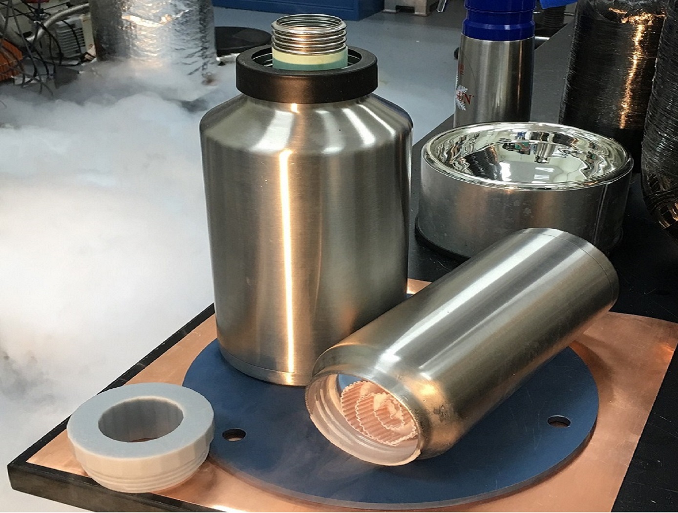
Cryogenic Flux Capacitor
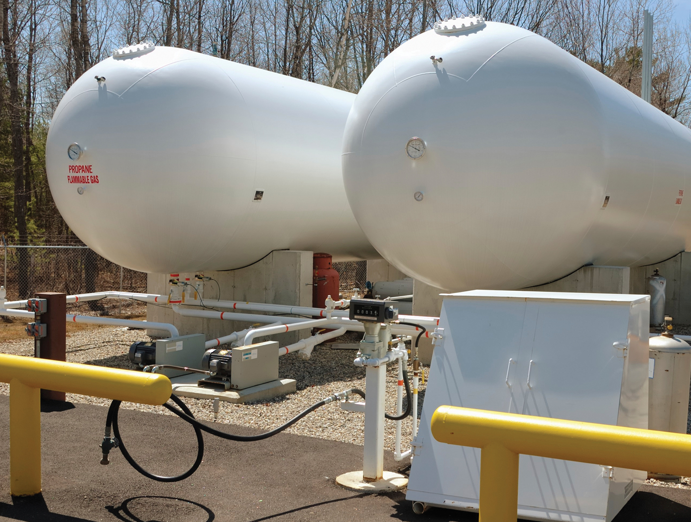
Storage and transfer of fluid commodities such as oxygen, hydrogen, natural gas, nitrogen, argon, etc. is an absolute necessity in virtually every industry on Earth. These fluids are typically contained in one of two ways; as low pressure, cryogenic liquids, or as a high pressure gases. Energy storage is not useful unless the energy can be practically obtained ("un-stored") as needed. Here the goal is to store as many fluid molecules as possible in the smallest, lightest weight volume possible; and to supply ("un-store") those molecules on demand as needed in the end-use application. The CFC concept addresses this dual storage/usage problem with an elegant charging/discharging design approach.
The CFC's packaging is ingeniously designed, tightly packing aerogel composite materials within a container allows for a greater amount of storage media to be packed densely and strategically. An integrated conductive membrane also acts as a highly effective heat exchanger that easily distributes heat through the entire container to discharge the CFC quickly, it can also be interfaced to a cooling source for convenient system charging; this feature also allows the fluid to easily saturate the container for fast charging. Additionally, the unit can be charged either with cryogenic liquid or from an ambient temperature gas supply, depending on the desired manner of refrigeration. Finally, the heater integration system offers two promising methods, both of which have been fabricated and tested, to evenly distribute heat throughout the entire core, both axially and radially.
NASA engineers also applied the CFC to a Cryogenic Oxygen Storage Module to store oxygen in solid-state form and deliver it as a gas to an end-use environmental control and/or life support system. The Module can scrub out nuisance or containment gases such as carbon dioxide and/or water vapor in conjunction with supplying oxygen, forming a synergistic system when used in a closed-loop application. The combination of these capabilities to work simultaneously may allow for reduced system volume, mass, complexity, and cost of a breathing device.
materials and coatings
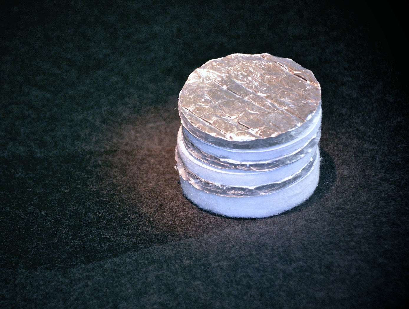
Layered Composite Insulation for Extreme Conditions (LCX)
The approach in developing the LCX system was to provide a combination of advantages in thermal performance, structural capability, and operations. The system is particularly suited for the complex piping, tanks, and apparatus subjected to the ambient environment common in the aerospace industry. The low-cost approach also lends the same technology to industrial applications such as building construction and chilled-water piping. The system can increase reliability and reduce life cycle costs by mitigating moisture intrusion and preventing the resulting corrosion that plagues subambient-temperature insulation systems operating in the ambient (humidity and rain) environment. Accumulated internal water is allowed to drain and release naturally over the systems normal thermal cycles. The thermal insulation system has a long life expectancy because all layer materials are hydrophobic or otherwise waterproof. LCX systems do not need to be perfectly sealed to handle rain, moisture accumulation, or condensation.
Mechanically, the LCX system not only withstands impact, vibration, and the stresses of thermal expansion and contraction, but can help support pipes and other structures, all while maintaining its thermal insulation effectiveness. Conventional insulation systems are notoriously difficult to manage around pipe supports because of the cracking and damage that can occur. Used alone or inside another structure or panel, the LCX layering approach can be tailored to provide additional acoustic or vibration damping as a dual function with the thermal insulating benefits. Because LCX systems do not require complete sealing from the weather, it costs less to install. The materials are generally removable, reusable, and recyclable, a feature not possible with other insulation systems. This feature allows removable insulation covers for valves, flanges, and other components (invaluable benefits for servicing or inspection) to be part of original designs.
Thermal performance of the LCX system has been shown to equal or exceed that of the best polyurethane foam systems, which can degrade significantly during the first two years of operation. With its inherent springiness, the system allows for simpler installation and, more importantly, better thermal insulation because of its consistency and full contact with the cold surface. Improved contact with the cold surface and better closure of gaps and seams are the keys to superior thermal performance in real systems. Eliminating the requirement for glues, sealants, mastics, expansion joints, and vapor barriers provides dramatic savings in material and labor costs of the installed system.
sensors
Low-Profile Wireless Sensor
The low-profile sensor is configured with a spiral electrical trace on flexible substrate. In typical inductor designs, the space between traces is designed to minimize parasitic conductance to reduce the impact of the capacitance to neighboring electronics. In the low-profile sensor, however, greater capacitance is desired to allow the operation of an inductor-capacitor circuit. This allows the traces to be closer together, decreasing the
overall size of the spiral trace.
The sensor receives a signal from the accompanying magnetic field data acquisition system. Once electrically active, the sensor produces its own harmonic magnetic field as the inductor stores and releases magnetic energy. The antenna of the measurement acquisition system is switched from a transmitting to a receiving mode to acquire the magnetic-field response of the sensor. The magnetic-field response attributes of frequency, amplitude, and bandwidth of the inductor correspond to the physical property states measured by the sensor. The received response is correlated to calibration data to determine the physical property measurement. When multiple sensors are inductively coupled, the data acquisition system needs to activate and read
only one sensor to obtain measurement data from all of them.
Electrical and Electronics

Broadband Metamaterial Termination for Planar Superconducting Transmission Line Circuits
The broadband metamaterial termination for use in planar superconducting transmission lines has been successfully demonstrated in CLASS circuit structures as an effective termination. This metamaterial implementation is fully compatible with microfabrication techniques commonly used for microwave circuitry, and its response is insensitive to geometric tolerances, material properties, and interface details of conductive elements in device fabrication. In the context of far-infrared imaging, polarimetric, and superconducting integral field unit (IFU) spectrometer arrays for astrophysics, this strategy leads to higher performance, increased device yield, and greater overall circuit density.
The metamaterial termination achieves a broadband absorption response with lower reflectance in a smaller physical footprint compared to existing adiabatic structures. This absorption response demonstrates significantly lower sensitivity to fabrication tolerances, material properties, and modeling assumptions than previous designs. These characteristics are critical for cryogenic applications, but the termination can also enhance the performance of room-temperature planar transmission line structures used in microwave engineering. The termination is realized as a lossy stepped impedance transition between Nb and PdAu, which reduces the total meander length, device footprint, and sensitivity to detailed implementation.
This broadband metamaterial termination is applicable in superconducting technologies, including quantum communications, computing, and sensors. It has reached Technology Readiness Level (TRL) 7 (technology demonstrated in an operational environment) and is now available for patent licensing.
Mechanical and Fluid Systems
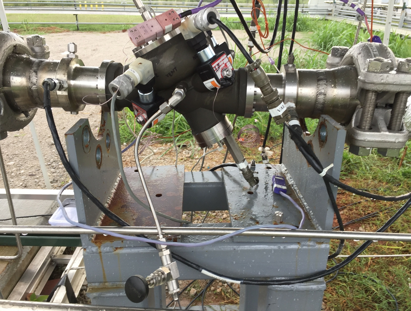
Cryogenic Hydraulically Actuated Isolation Valve
NASA's cryogenic isolation valve technology uses solenoid valves powered by direct current (DC) electrical energy to control and redirect the energy stored in the upstream line pressure. Powering the solenoid valves only requires a DC power source capable of supplying 22 watts that can be distributed and controlled in an on/off manner. By achieving actuation using only upstream line pressure and a 22-watt DC power source, many additional support systems that are required for electromechanical and pneumatic actuation are eliminated. This reduction of parts results in several benefits, including reduced footprint, weight, and potential cost of the valve in addition to lower energy consumption.
NASA fabricated several operational prototype valves using this technology for a rocket company. The table below shows the results of tests performed on these valves under cryogenic conditions. Please contact the NASA MSFC Technology Transfer Office for additional information.
mechanical and fluid systems
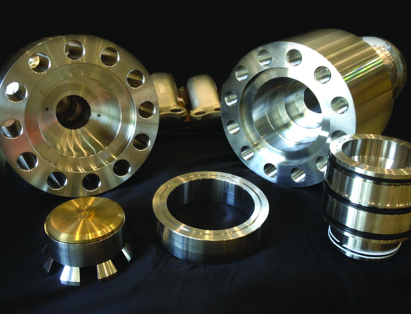
Floating Piston Valve
Instead of looking to improve current valve designs, a new type of valve was conceived that not only addresses recurring failures but could operate at very high pressures and flow rates, while maintaining high reliability and longevity. The valve design is applicable for pressures ranging from 15-15,000+ psi, and incorporates a floating piston design, used for controlling a flow of a pressurized working fluid.
The balanced, floating piston valve design has a wide range of potential applications in all sizes and pressure ranges. The extremely simple design and few parts makes the design inherently reliable, simple to manufacture, and easy to maintain. The valve concept works with soft or hard metal seats, and the closing force is easily adjustable so that any closing force desired can be created. The fact that no adjustment is required in the design, ensures valve performance throughout valve life and operation.
This valve has many unique features and design advantages over conventional valve concepts:
- The largest advantage is the elimination of the valve stem and any conventional actuator, reduces physical size and cost.
- It is constructed with only 5 parts.
- It eliminates the need for many seals, which reduces failure, downtime and maintenance while increasing reliability and seat life.
- The flow path is always axially and radially symmetric, eliminating almost all of the flow induced thrust loads - even during transition from closed to open.
Manufacturing

Ultra-low Reflectivity Black Silicon Pupil Masks
Fabrication of NASA's pupil mask begins with the preparation of a silicon wafer, which serves as the foundation for the black silicon structure. The wafer undergoes ion beam figuring (IBF), a non-contact technique that precisely removes surface irregularities at the nanometer scale. This process ensures that the silicon surface is diffraction-limited, eliminating errors that could degrade optical performance. Once the wafer is polished to the required precision, it is then processed lithographically to define the mask pattern, creating reflective and absorptive regions essential for controlling light propagation.
To achieve the desired high absorption characteristics, the lithographically patterned wafer undergoes cryogenic etching, a sophisticated process that transforms the silicon surface into a highly textured, black silicon structure. This method utilizes a controlled plasma environment with sulfur hexafluoride (SF6) and oxygen to etch the surface at cryogenic temperatures. The process is carefully optimized by adjusting parameters such as gas flow rates, chamber pressure, ion density, and etch duration, leading to the formation of high-aspect-ratio nanostructures on the silicon substrate. These structures, resembling a dense “forest” of silicon nanospikes, trap and diffuse incoming light, drastically reducing specular reflection. The resulting surface exhibits an ultra-low reflectivity that is orders of magnitude lower than conventional polished silicon.
By leveraging NASA’s cutting-edge fabrication technique, the newly developed black silicon pupil mask offers a powerful solution for high-contrast astronomical imaging. Its ability to minimize scattered light and enhance optical contrast makes it an ideal component for space telescopes tasked with directly imaging exoplanets as well as other applications requiring ultra low reflectivity systems.

