Capacitive Micro-Gravity Fluid Mass Gauge
Instrumentation
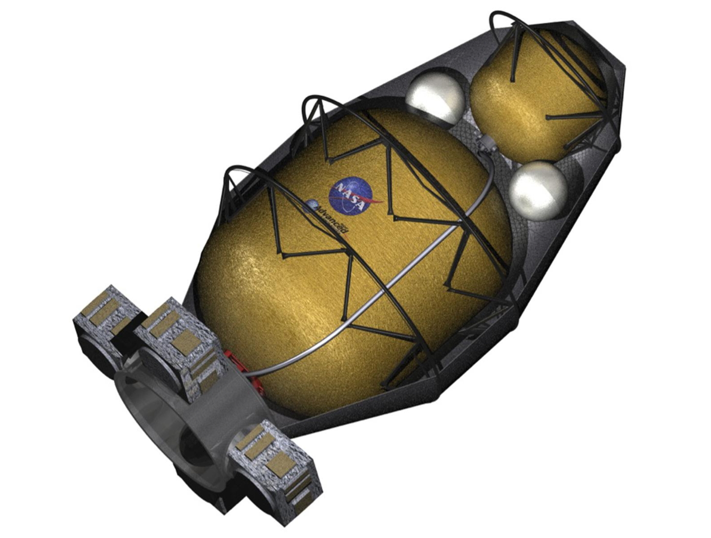
Capacitive Micro-Gravity Fluid Mass Gauge (KSC-TOPS-96)
An Accurate Method of Measuring Fluid or Gas Inside a Vessel
Overview
Measuring fluid mass in micro gravity, where fluid behavior is dominated by fluid properties, is a challenging problem. To address this problem engineers at NASA are developing a capacitance-based, mass-fraction gauge for vessels containing two-phase fluids. The vessel volume is enclosed with an array of electrodes, and a unique set of capacitance measurements of the enclosed volume are made between the electrodes. The capacitance measurements are scaled with appropriate weighting factors derived from Laplace's Equation to compensate for the highly non-uniform electric fields inside the measurement volume and achieve a greater level of mass fraction accuracy.
The Technology
The capacitive micro-gravity fluid mass gauge with spatial regularization is a sensor that can be outfitted to propellant vessels and can provide a determination of the mass of liquid and gas inside the vessel volume with a determinable level of accuracy. The sensor consists of 1) a number of discrete electrodes that are installed to the inner surface of the vessel wall, 2) signal generating, digitizing, signal conditioning, and general support (e.g., power supply) electronics, 3) electrical connections between the electrodes and the electronics, and 4) the algorithm used to turn the set of capacitance measurements (i.e., the capacitance matrix) into a volume fraction. The electronics generate and apply a sinusoid to a single electrode, and then the electronics measure the charge on all other electrodes. Capacitance is simply the charge divided by the voltage. This is repeated for all electrodes, without repeating duplicates. For a vessel with a fixed volume, the volume fraction can be converted to the mass fraction using the Ideal Gas Law so long as the fluid constituents, temperature, and pressure are known.
Benefits
- Accurately Measures Fluid Mass
- Senses Entire Tank Volume
- Scalable to Different Sized Tanks
Applications
- Tank and Vessel Transport
- Gas and Liquid Systems
- LNG Storage
- Hydrogen Storage
- Cryogenic Liquids Storage
Technology Details
Instrumentation
KSC-TOPS-96
KSC-14530
https://ntrs.nasa.gov/api/citations/20230002779/downloads/CAPMAG%20SCW%20Abstract.docx.pdf
ARC Article: https://arc.aiaa.org/doi/10.2514/1.A36181
IOP Article: https://iopscience.iop.org/article/10.1088/1361-6501/aca0b1
Similar Results

System and Method for Fluid Dynamic Mass Gauging
Fluid Dynamic Mass Gauging (FDMG) is a microgravity-compatible system that applies principles of fluid dynamics, the ideal gas law, and thermodynamics to determine the volume of an incompressible fluid within a tank by measuring the compressible volume in the same tank. In a simplified embodiment, the determination of the remaining volume of the fluid within a given storage tank can be calculated from a time measurement of a pressure change during a filling or venting process applied to the storage tank. The process may be automated and features low mass and volume requirements, enabling its use in any gravitational or inertial environment with minimal hardware modifications. The novel system can determine the volume of a non-condensing, incompressible fluid within a rigid tank of known or unknown volume without requiring the use of bulky equipment in microgravity locations with fixed or limited free space.

Fluid Measurement Sensor
The fluid measurement sensor is configured with a spiral electrical trace on flexible substrate. The sensor receives a signal from the accompanying magnetic field data acquisition system. Once electrically active, the sensor produces its own harmonic magnetic field as the inductor stores and releases magnetic energy. The antenna of the measurement acquisition system is switched from transmitting to receiving mode to acquire the magnetic-field response of the sensor. The magnetic-field response attributes of frequency, amplitude, and bandwidth of the inductor correspond to the physical property states measured by the sensor. The received response is correlated to calibrated data to determine the physical property measurement. When multiple sensors are inductively coupled, the data acquisition system only needs to activate and read one sensor to obtain measurement data from all of them.
Fluid level measurement occurs in several ways. In the immersion method, the capacitance of the sensor circuit changes as it is immersed in fluid, thus changing the frequency response as the fluid level rises or falls. Fluid level can also be measured from the outside of a non-conductive container. The response frequency from the sensor is dependent upon the inductance of the container plus the combination of fluid and air inside it, which corresponds to the level of liquid inside the container. Roll and pitch are measured by using three or more sensors in a container. With any given orientation, each sensor will detect a different fluid level, thus providing the basis for calculating the fluid angle. Volume can be measured in the same way, using the angle
levels detected by the sensors and the geometric characteristics of the container to perform the volume calculation.
.jpg)
Fluid-Filled Frequency-Tunable Mass Damper
NASA MSFC’s Fluid-Filled Frequency-Tunable Mass Damper (FTMD) technology implements a fluid-based mitigation system where the working mass is all or a portion of the fluid mass that is contained within the geometric configuration of either a channel, pipe, tube, duct and/or similar type structure. A compressible mechanism attached at one end of the geometric configuration structure enables minor adjustments that can produce large effects on the frequency and/or response attributes of the mitigation system.
Existing fluid-based technologies like Tuned Liquid Dampers (TLD) and Tuned Liquid Column Dampers (TLCD) rely upon the geometry of a container to establish mitigation frequency and internal fluid loss mechanisms to set the fundamental mitigation attributes. The FTMD offers an innovative replacement since the frequency of mitigation and mitigation attributes are established by the compressible mechanism at the end of the container. This allows for simple alterations of the compressible mechanism to make frequency adjustments with relative ease and quickness.
FTMDs were recently successfully installed on a building in Brooklyn, NYC as a replacement for a metallic TMD, and on a semi-submersible marine-based wind turbine in Maine.
The FTMD technology is available for non-exclusive licensing and partially-exclusive licensing (outside of building construction over 300 feet).

Micro-Organ Device Mimics Organ Structures for Lab Testing
The MOD platform technology represents a small, lightweight, and reproducible in vitro drug screening model that could inexpensively mimic different mammalian tissues for a multitude of applications. The technology is automated and imposes minimal demands for resources (power, analytes, and fluids). The MOD technology uses titanium isopropoxide to bond a microscale support to a substrate and uses biopatterning and 3D tissue bioprinting on a microfluidic microchip to eliminate variations in local seeding density while minimizing selection pressure. With the MOD, pharmaceutical companies can test more candidates and concentrate on those with more promise therefore, reducing R&D overall cost.
This innovation overcomes major disadvantages of conventional in vitro and in vivo experimentation for purposes of investigating effects of medicines, toxins, and possibly other foreign substances. For example, the MOD platform technology could host life-like miniature assemblies of human cells and the effects observed in tests performed could potentially be extrapolated more readily to humans than could effects observed in conventional in vivo cell cultures, making it possible to reduce or eliminate experimentation on animals.
The automated NASA developed technology with minimal footprint and power requirements, micro-volumes of fluids and waste, high throughput and parallel analyses on the same chip, could advance the research and development for new drugs and materials.

Streamlined Liquid Level Sensing Using Fiber Optics
Armstrong has developed a robust fiber optic–based sensing technology that offers extraordinary accuracy in liquid level measurements. The sensing system uses fiber optic Bragg sensors located along a single fiber optic cable. These sensors actively discern between the liquid and gas states along a continuous fiber and can accurately pinpoint the liquid level.
How It Works
The technology uses a resistive heater wire bundled with the optical fiber. The heater is pulsed to induce a local temperature change along the fiber, and the fiber Bragg grating data is used to monitor the subsequent cooling of the fiber. The length of fiber in the liquid cools more rapidly than the portion of the fiber in the gas above the liquid. The measurement system accurately establishes the location of this transition to within 1/4-inch.
Why It Is Better
Armstrong's liquid level sensing technology was originally developed to measure cryogenic liquid levels in rockets, and it represents a significant advancement in the state of the art in this application. Conventional methods for measuring cryogenic liquid levels rely on cryogenic diodes strategically placed along a rod or rack. The diodes are mounted in pre-selected, relatively widely spaced positions along the length of a rod; this configuration provides limited, imprecise data. Furthermore, each diode on the rod has two wires associated with it, which means a single system may require a large number of wires, making installation, connectivity, and instrumentation cumbersome.
Armstrong's novel technology provides liquid measurements with much greater precision, achieving measurements at 1/4-inch intervals. Furthermore, the streamlined system uses just two wires, which greatly simplifies installation and instrumentation. Due to its extraordinary accuracy and ease of use, Armstrong's measurement system offers important advantages for a wide range of applications beyond cryogenic liquids.
In Addition
Researchers have developed a new manufacturing process that improves the ability of fiber optic sensing systems to measure temperature and liquid levels when operating in humid environments. The process involves eliminating moisture from the optical fiber coating, then completing the sensor assembly within humidity-controlled conditions. The resulting sensor hardware provides precise and accurate measurements even when operating in a humid environment.
For more information about the full portfolio of FOSS technologies, see DRC-TOPS-37 or visit https://technology-afrc.ndc.nasa.gov/featurestory/fiber-optic-sensing

