Search
Instrumentation

LED Intensity Decay Particle Tracking Velocimetry (PTV)
NASA’s LED-ID PTV system illuminates a seeded flow with an LED rather than a laser. Instead of using double-pulsed laser flashes to capture two separate images of particle positions, the system relies on the inherent intensity decay of an LED pulse to encode velocity information directly into a single long-exposure image. The LED’s light intensity decreases over time due to capacitor discharge characteristics of the driving circuit. This controlled decay serves as a built-in intensity marker, allowing for precise determination of particle velocity and directionality without requiring an actively modulated light source.
In a single-color configuration, a monochrome camera captures a long- exposure image of particle streaks as they move through the illuminated region. Because the light intensity is continuously decreasing, the recorded streaks naturally encode velocity information based on their brightness gradient. Faster-moving particles create longer streaks, while slower particles form shorter ones. The intensity variation across the streak provides additional data about directionality, enabling flow field analysis with a minimal hardware setup. For more complex flow analysis, a two-color configuration can be employed to track three- dimensional motion. In this setup, two LEDs of different colors are positioned adjacent to each other to create overlapping light sheets. A color camera, or two monochrome cameras with a dichroic mirror, captures the streaks of particles as they move between these sheets.
The color transition within a particle’s streak indicates its movement between the planes of illumination, allowing users to resolve out-of- plane velocity components. Image processing techniques (e.g., advanced algorithms, high-pass filtering methods, sub-interval streak segmentation) further enhance the system's accuracy.
NASA’s LED-ID PTV system has been prototyped and demonstrated with excellent results, and is available for patent licensing to industry.
sensors

Cord Tension Measurement Device (C-Gauge)
The C-Gauge is made of a 3D-printed aluminum body with strain gauges attached to the inner and outer walls of the connecting beam. The legs of the gauge attach firmly to the cord. When the cord is stretched, the tension in the cord goes through the legs and into the beam, causing it to bend. This bending creates a tension and compression stress in the bottom and top surface of the beam, respectively. The strain gauges capture the tension and compression, which are then used to determine the tension in the cord. The use of multiple strain gauges mitigates any torsion loading of the gauge and provides a direct measurement of the axial tension load of the cord.
The C-Gauge is a low-profile, non-invasive system that can be installed onto an existing cord in a system (e.g., the suspension, reefing, or riser lines in a parachute) without the need to remove or re-install the cord. It is small and lightweight and does not add stiffness or weight to the cord and thus does not affect the dynamics of the parachute or the structural response of the system. The C-Gauge can be scaled to larger and smaller sizes to measure larger and smaller load capabilities, dependent on the cord.
The C-Gauge is at a TRL 4 (component and/or breadboard validation in a laboratory environment) and it is now available for your company to license and develop into a commercial product. Please note that NASA does not manufacture products itself for commercial sale.
Materials and Coatings

Waveguide-based Dielectric and Magnetic Property Measurement
This NASA invention utilizes a simple waveguide-based measurement system to determine the complex dielectric permittivity and magnetic permeability of arbitrary-shaped planetary rock samples. The system operates at L-band frequencies (~1 GHz) and can be extended to P- and S-bands for broader applications. The approach involves placing an arbitrarily-shaped sample inside an open-ended waveguide excited by a coaxial probe, measuring the scattering parameters, and extracting dielectric and magnetic properties through computational modeling and optimization techniques.
A key aspect of this system is its ability to handle non-uniform and irregularly shaped rock samples, enabling the measurement of real-world planetary materials without requiring extensive sample preparation. The methodology includes calibration in an anechoic chamber, computational modeling, and iterative refinement of measured vs. simulated scattering parameters to extract the material properties.
Future advancements will involve expanding measurements to different frequency bands, refining computational models using artificial intelligence, and automatically rotating samples within the waveguide to obtain multiple directional measurements (enhancing precision while reducing test time).
This NASA innovation has been successfully applied to two Martian meteorite samples, yielding values of dielectric permittivity and permeability relevant for Mars radar applications. The system will further be leveraged to build an expansive database of the dielectric properties of planetary soils and rocks to improve radar-based mapping (e.g., subsurface mapping) missions. The invention could also be applied for the non-destructive screening of a variety of samples using radio waves, including biological samples for medical purposes, additive manufacturing feedstock or finished parts, and mining-related rock samples to test for impurities or resources of interest. This NASA invention is at technology readiness level (TRL) 5 (component and/or breadboard validation in relevant environment) and is available for patent licensing.
Electrical and Electronics

Self-Adjusting Gap System for Charge Mitigation and Monitoring
Fixed-point or spark-plug discharge systems are challenging to set up and maintain, often suffering from performance degradation or failure as repeated discharges damage and alter contact points. Similarly, contact-based solutions like slip rings can introduce torque drag and create contamination particles over time as materials wear down. The SAG system eliminates these problems with its innovative contactless design, proven to cycle reliably tens of thousands of times without failure. In testing, this system survived approximately 25,000 times the expected mission charge cycles.
The SAG system consists of a flexure, discharge point, and bleed circuit that controls the voltage, location and current at which a discharge occurs. The flexure is electrically isolated from the rest of the stationary body forcing the discharge current to go through the bleed circuit. This provides the ability to protect sensitive electronics from a sudden field collapse or ground plane disturbance. The flexure is able of taking different forms depending on the application and desired characteristics allowing for a scalable system, modifiable for various mission parameters. Additionally, the SAG system is passive until needed, requiring no active electronics unless used as a sensor. Due to its contactless nature, the SAG system simplifies live wear testing, significantly lowering costs compared to traditional mechanisms. Unlike fixed-point systems, it does not require precise dynamic clearances, making it more tolerant to launch loads and reducing the severity of electrical discharge events.
Although designed for space and planetary exploration applications, the SAG system may also be valuable for terrestrial use cases for monitoring charging of electrically isolated components where charge buildup may occur or where grounding isn’t possible. The SAG System is at technology readiness level (TRL) 6 (system demonstration in relevant environment) and is available for patent licensing.
Optics

Filtered Ronchi Rulings for Enhanced Schlieren Imaging
The first optic is a 1D Ronchi ruling, where shortpass or longpass filters replace the traditional opaque lines in the grid pattern. The second optic is a 2D Ronchi ruling, where one set of lines is made from shortpass filters and the orthogonal set from longpass filters. By using two colors of light and a color camera in the focusing schlieren system (or a dichroic mirror with two monochrome cameras), the 1D optic enables simultaneous focusing schlieren and other co-linear techniques, while the 2D optic allows for the unambiguous measurement of two orthogonal density gradients in focusing schlieren images.
Unlike standard optical filters, which typically cover an entire substrate, these Ronchi rulings feature alternating clear and filtered regions in structured 1D or 2D patterns. By leveraging color filtering and a color camera, the 1D ruling enables simultaneous focusing schlieren and complementary optical diagnostics, such as Particle Image Velocimetry (PIV), Pressure-Sensitive Paint (PSP), and Thermal-Sensitive Paint (TSP). The 2D ruling enables simultaneous and unambiguous measurement of two orthogonal density gradients, a capability not possible with conventional Ronchi rulings. This advancement significantly improves the accuracy and efficiency of schlieren-based flow measurements. The types of filters are not just limited to shortpass and longpass coatings, but could include notch, bandpass, and multiple-bandpass filter coatings as well.
This design expands the utility of schlieren imaging in high-speed aerodynamics, combustion diagnostics, and other fluid dynamics applications. This Ronchi ruling methodology is at TRL 4 (component and/or breadboard validation in a lab environment) and is available for patent licensing.
instrumentation
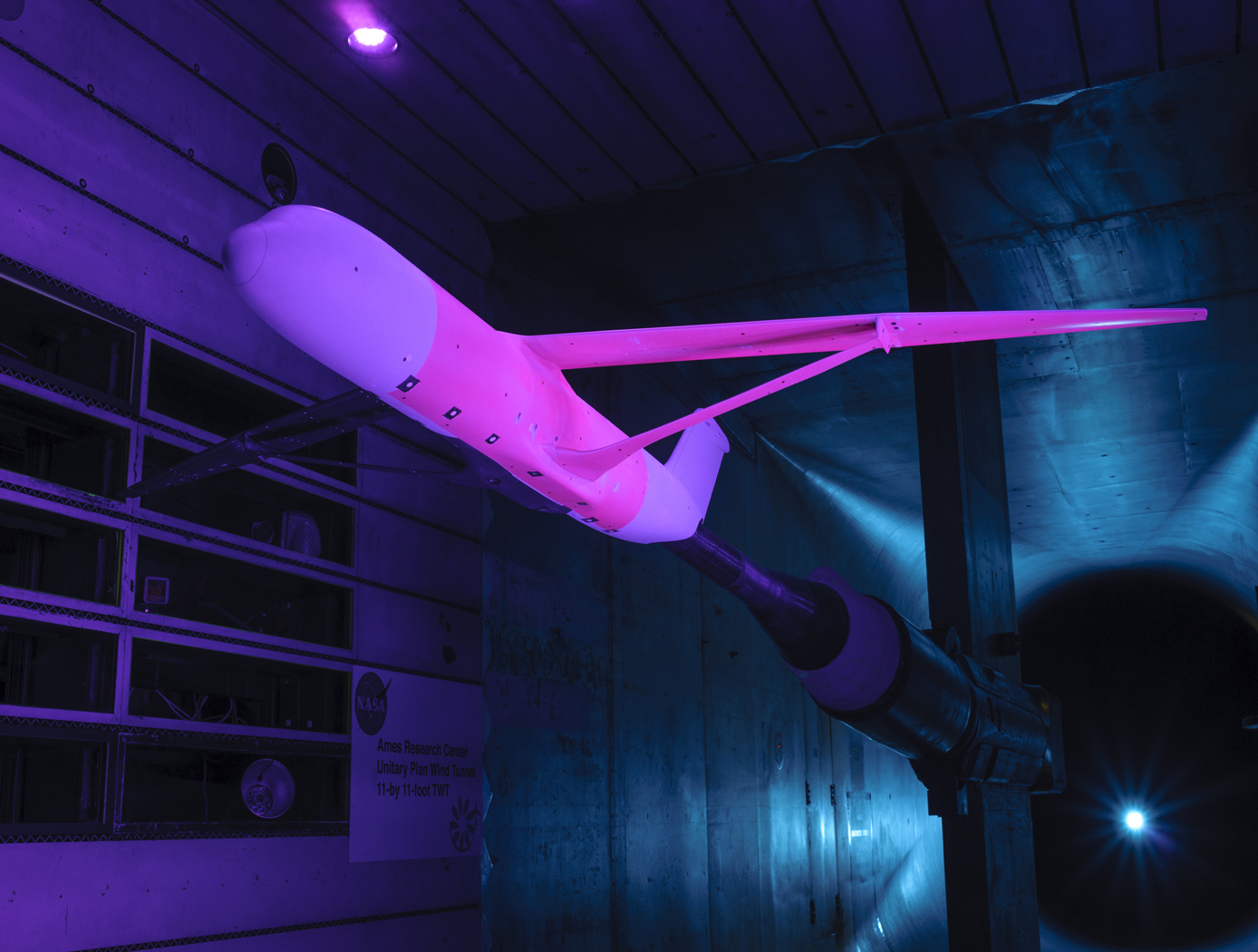
Calculation of Unsteady Aerodynamic Loads Using Fast-Response Pressure-Sensitive Paint (PSP)
Traditionally, unsteady pressure transducers have been the instrumentation of choice for investigating unsteady flow phenomena which can be time-consuming and expensive. The ability to measure and compute these flows has been a long-term challenge for aerospace vehicle designers and manufacturers. Results using only the pressure transducers are prone to inaccuracies, providing overly conservative load predictions in some cases and underestimating load predictions in other areas depending on the flow characteristics. NASA Ames has developed a new state-of-the-art method for measuring fluctuating aerodynamic-induced pressures on wind tunnel models using unsteady Pressure Sensitive Paint (uPSP). The technology couples recent advances in high-speed cameras, high-powered energy sources, and fast response pressure-sensitive paint. The unsteady pressure-sensitive paint (uPSP) technique has emerged as a powerful tool to measure flow, enabling time-resolved measurements of unsteady pressure fluctuations within a dense grid of spatial points on a wind tunnel model. The invention includes details surrounding uPSP processing. This technique enables time-resolved measurements of unsteady pressure fluctuations within a dense grid of spatial points representing the wind tunnel model. Since uPSP is applied by a spray gun, it is continuously distributed. With this approach, if the model geometry can be painted, viewed from a camera, and excited by a lamp source, uPSP data can be collected. Unsteady PSP (uPSP) has the ability to determine more accurate integrated unsteady loads.
manufacturing
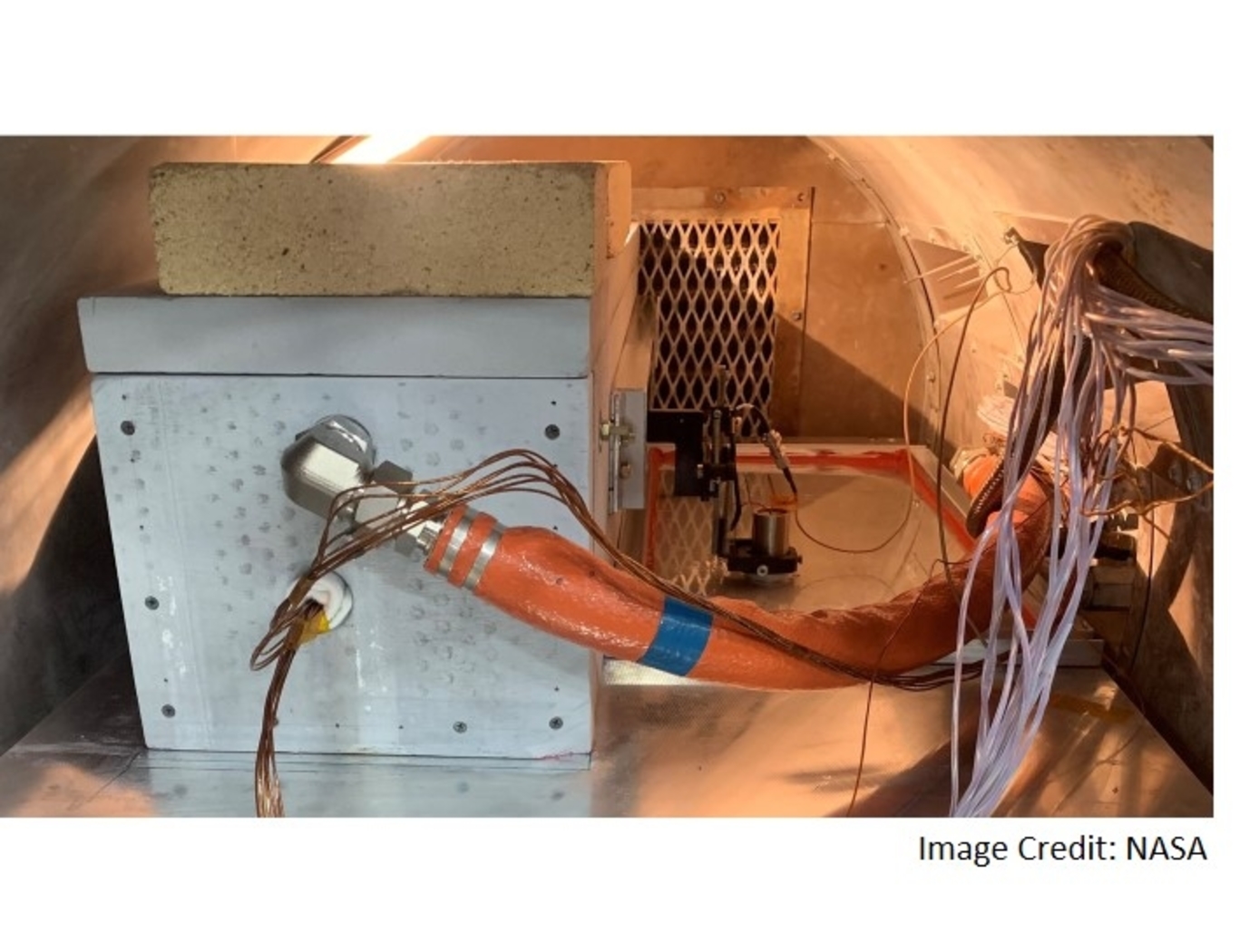
System for In-situ Defect Detection in Composites During Cure
NASA's System for In-situ Defect (e.g., porosity, fiber waviness) Detection in Composites During Cure consists of an ultrasonic portable automated C-Scan system with an attached ultrasonic contact probe. This scanner is placed inside of an insulated vessel that protects the temperature-sensitive components of the scanner. A liquid nitrogen cooling systems keeps the interior of the vessel below 38°C. A motorized X-Y raster scanner is mounted inside an unsealed cooling container made of porous insulation boards with a cantilever scanning arm protruding out of the cooling container through a slot. The cooling container that houses the X-Y raster scanner is periodically cooled using a liquid nitrogen (LN2) delivery system. Flexible bellows in the slot opening of the box minimize heat transfer between the box and the external autoclave environment. The box and scanning arm are located on a precision cast tool plate. A thin layer of ultrasonic couplant is placed between the transducer and the tool plate. The composite parts are vacuum bagged on the other side of the tool plate and inspected. The scanning system inside of the vessel is connected to the controller outside of the autoclave. The system can provide A-scan, B-scan, and C-scan images of the composite panel at multiple times during the cure process.
The in-situ system provides higher resolution data to find, characterize, and track defects during cure better than other cure monitoring techniques. In addition, this system also shows the through-thickness location of any composite manufacturing defects during cure with real-time localization and tracking. This has been demonstrated for both intentionally introduced porosity (i.e., trapped during layup) as well processing induced porosity (e.g., resulting from uneven pressure distribution on a part). The technology can be used as a non-destructive evaluation system when making composite parts in in an oven or an autoclave, including thermosets, thermoplastics, composite laminates, high-temperature resins, and ceramics.
sensors
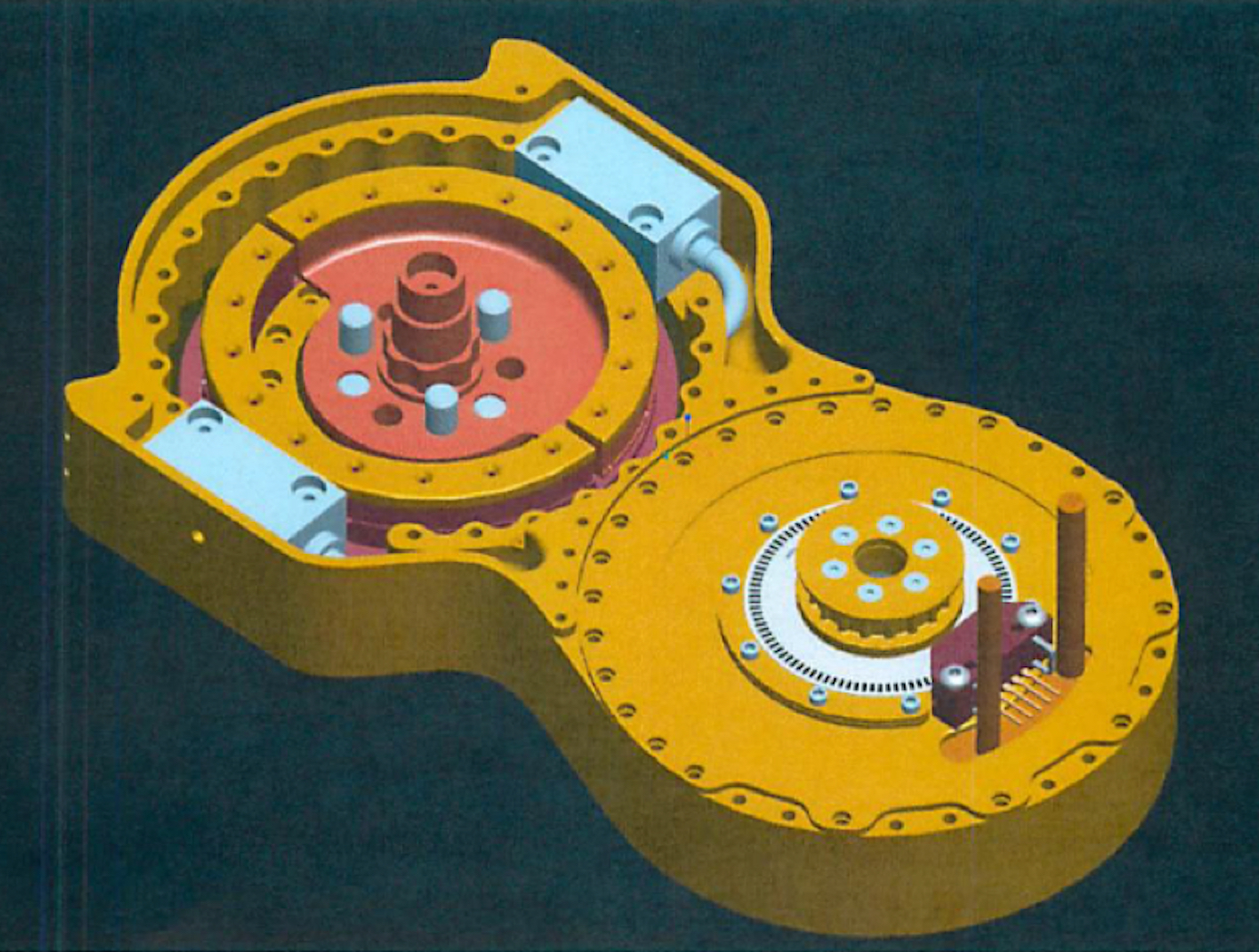
Split-Ring Torque Sensor
The SRTS enables measurement of position, velocity, and torque of a rotating system (e.g., actuator, motor, crankshaft, rotor, etc.) using two optical sensors and a single, custom-designed split-ring rather than the standard dual-ringed systems commonly used for similar applications. The split-ring is comprised of two structural arcs positioned in a concentric, coplanar relationship, wherein each arc is attached to a component capable of rotation (e.g., a lower leg and upper leg, where the SRTS acts as a knee). The two arcs contain indications or codes on their outer surfaces that are read by the optical sensors to determine the relative deflection of the structural arcs as they rotate.
The SRTS configuration discussed above is limited to 180-degree applications. The addition of a third structural arc and a third optical reader, however, would enable 360-degree functionality.
Tests have shown the SRTS has a high degree of tolerance to temperature differences and provides higher resolution measurements than competing technologies.
Electrical and Electronics

Enhanced DC Bus Emulator
Combining a dynamic load emulation technique with a PWM dithering technique, NASA’s technology provides a more efficient, cost-effective, and practical method to emulate complex loads. While there are commercially available electronic device loads on the market that meet basic emulation needs, these devices are limited; they are limited with respect to small input voltage changes, and to feedback signals from the device’s power system, which may lack the strength and resolution needed to emulate accurately.
A common solution for the bus emulation limitation is to construct a model of an actual microgrid using representative loads and connections. But this can be complex, costly, and have limitations in performance. NASA’s approach addresses these challenges without creating an actual model microgrid to replicate the systems.
As opposed to stand-alone COTS electronic load devices or model microgrids using representative loads and connections for a given test, NASA’s technology is a system constructed of an input power filter, a COTS electronic load device or load subsystem, and a power control circuit. The input power filter is designed to emulate load or bus performance at the medium to high frequency range. The power control circuit combined with the electronic load or load subsystem emulates lower frequency and constant power dynamics of the system. Lastly, the power control circuit linearizes digitization and quantization issues present with digitally controlled COTS electronic loads.
The power control circuit can be set to measure a load voltage, which is divided by a determined value for power, and combined with a triangle wave dither (the power control circuit block image demonstrates how to integrate a triangle wave dither). This dither dynamically adjusts the electrical current or power to keep it constant within the commercially purchased load device, enabling accurate emulation of complex DC microgrid systems.

