Search
mechanical and fluid systems

Liquid Sorbent Carbon Dioxide Removal System
NASA's Liquid Sorbent Carbon Dioxide Removal System was designed as an alternative to the current CO2 removal technology used on the International Space Station (ISS), which uses solid zeolite media that is prone to dusting, has a low absorption capacity, and requires high regeneration temperatures and frequent maintenance. Motivated by CO2 removal systems on submarines, NASA innovators began investigating the use of liquid sorbents. Liquid sorbents have a capacity four times greater than solid zeolites, require low regeneration temperature, and need fewer unreliable moving mechanical parts than solid based systems. While submarine CO2 scrubbers spray an adsorbing chemical directly into the air stream and allow the liquid to settle, NASA's new system uses a capillary driven 3D printed microchannel direct air/liquid contactor in a closed loop system. The Liquid Sorbent Carbon Dioxide Removal System is robust and reliable, while being low in weight, volume, and power requirements. The system is capable of reaching equilibrium when the liquid sorbent surface is being regenerated at a rate equal to the rate of absorption into the liquid.
Power Generation and Storage
Cryogenic Flux Capacitor
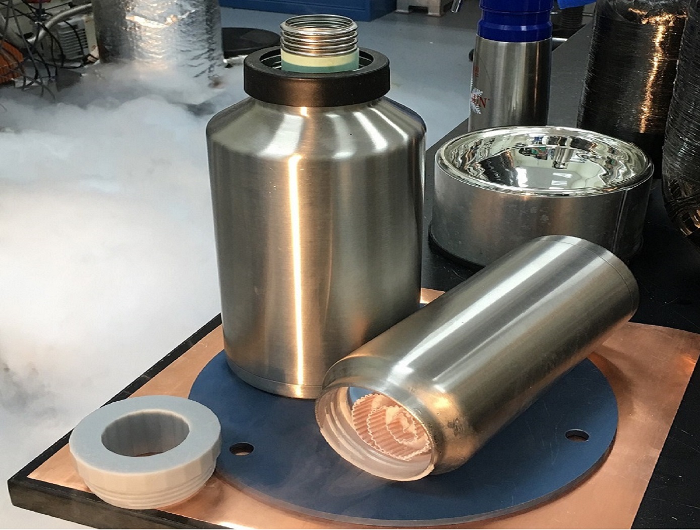
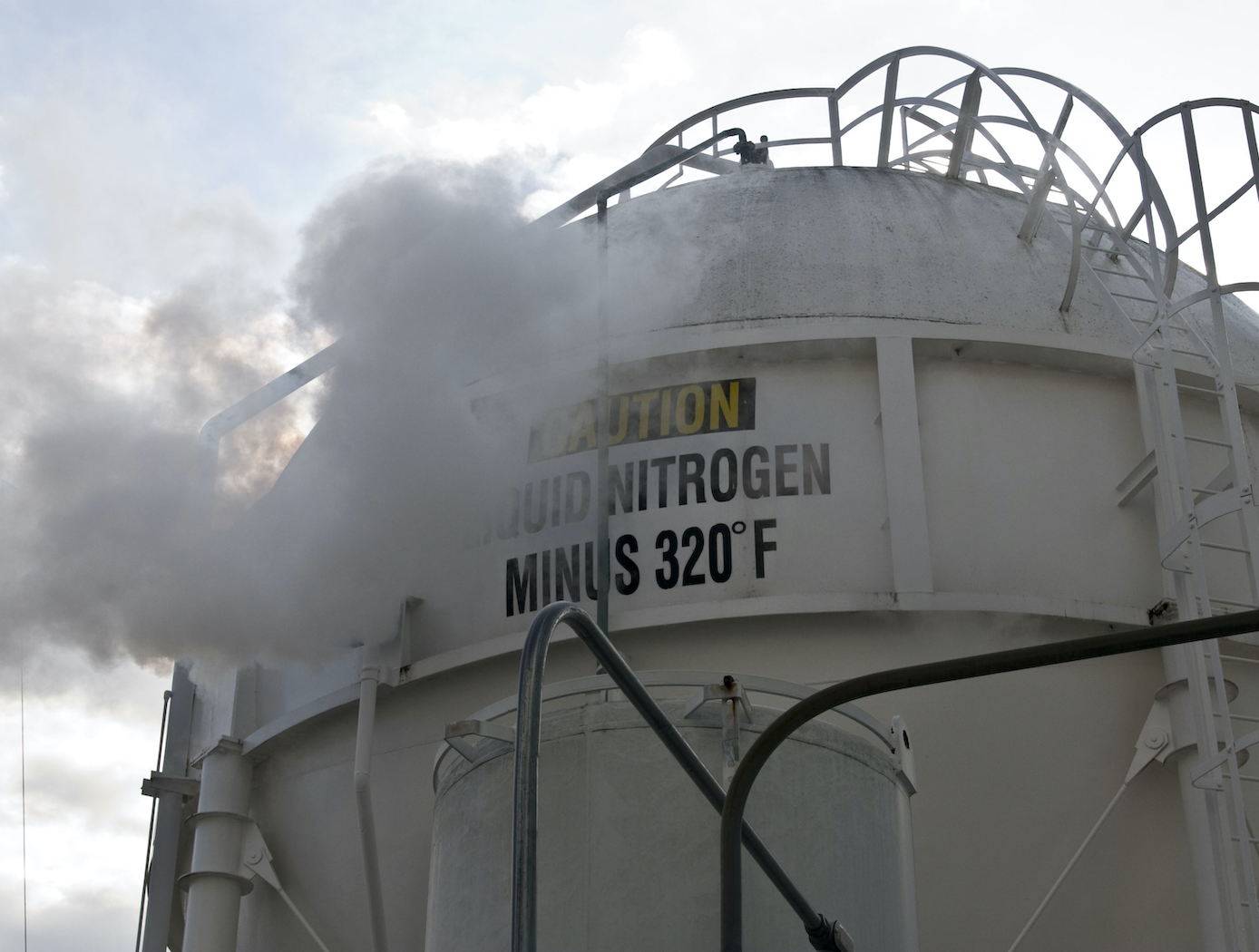
Storage and transfer of fluid commodities such as oxygen, hydrogen, natural gas, nitrogen, argon, etc. is an absolute necessity in virtually every industry on Earth. These fluids are typically contained in one of two ways; as low pressure, cryogenic liquids, or as a high pressure gases. Energy storage is not useful unless the energy can be practically obtained ("un-stored") as needed. Here the goal is to store as many fluid molecules as possible in the smallest, lightest weight volume possible; and to supply ("un-store") those molecules on demand as needed in the end-use application. The CFC concept addresses this dual storage/usage problem with an elegant charging/discharging design approach.
The CFC's packaging is ingeniously designed, tightly packing aerogel composite materials within a container allows for a greater amount of storage media to be packed densely and strategically. An integrated conductive membrane also acts as a highly effective heat exchanger that easily distributes heat through the entire container to discharge the CFC quickly, it can also be interfaced to a cooling source for convenient system charging; this feature also allows the fluid to easily saturate the container for fast charging. Additionally, the unit can be charged either with cryogenic liquid or from an ambient temperature gas supply, depending on the desired manner of refrigeration. Finally, the heater integration system offers two promising methods, both of which have been fabricated and tested, to evenly distribute heat throughout the entire core, both axially and radially.
NASA engineers also applied the CFC to a Cryogenic Oxygen Storage Module to store oxygen in solid-state form and deliver it as a gas to an end-use environmental control and/or life support system. The Module can scrub out nuisance or containment gases such as carbon dioxide and/or water vapor in conjunction with supplying oxygen, forming a synergistic system when used in a closed-loop application. The combination of these capabilities to work simultaneously may allow for reduced system volume, mass, complexity, and cost of a breathing device.
Mechanical and Fluid Systems
Pilot Assisted Check Valve for Low Pressure Applications
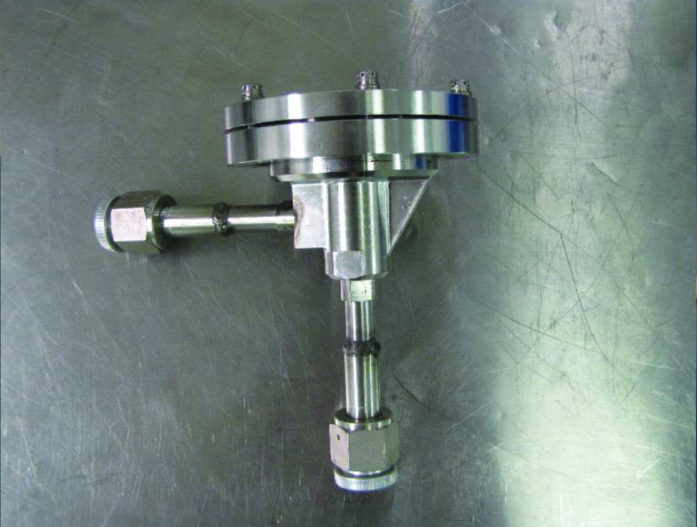
Check valves are traditionally designed as a simple poppet/spring system where the spring is designed to equal the force created from the sealing area of the valve seat multiplied by the cracking pressure. Since the valve seat diameter in these types of valves are relatively small, less than 0.5 inches diameter, a low cracking pressure required for back pressure relief devices results in a low spring preload. When sealing in the reverse direction, the typical 20 psid storage pressure of the cryogenic fluid is not enough pressure force to provide adequate sealing stress. To better control the cracking pressure and sealing force, a bellows mechanism was added to a poppet check valve (see Figure 2). The bellows serves as a reference pressure gauge; once the targeted pressure differential is reached, the bellows compresses and snaps the valve open. Prior to reaching the desired crack pressure differential, the bellows diaphragm is fully expanded, providing sufficient seal forces to prevent valve flow (including reverse flow) and undesired internal leakage. Room temperature testing of cracking pressure, full flow pressure, and flow capacity all showed improvements. The overall results of the test proved to be 10-20 times greater than conventional check valves with no internal leakage at three different pressure differentials.
Mechanical and Fluid Systems
3D-Printed Injector for Cryogenic Fluid Management
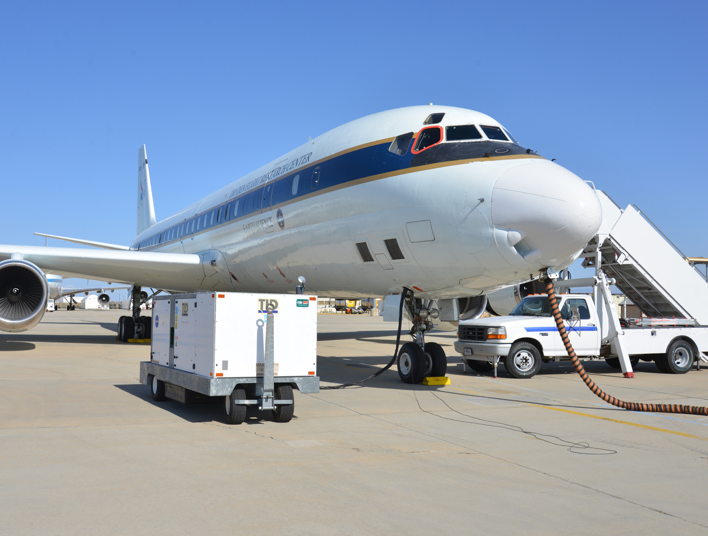
NASA's TVS Augmented Injector includes an internal heat exchanger, a fluid injector spray head, and an external surface condensation heat exchanger - all combined with multiple intertwined flow paths containing liquid, two-phase, and gaseous working fluid. The TVS provides a source of coolant to the injector, which chills the incoming fluid flow. This cooled flow promotes condensation of the tank ullage dropping pressure and maintains incoming fluid flow. The system eliminates the potential for a stalled fill condition and reduces tank pressure during cryogenic fluid transfer. During fill operations, the tank vent can be closed early in the process before fluid is introduced, and, in some cases, the tank vent may not even need to be opened. Furthermore, the TVS Augmented Injector can remove sufficient thermal energy to reach a 100% liquid level in the receiver tank. A cryo-cooler can be used in place the TVS flow circuit for a zero-loss system. The TVS Augmented Injector couples internal fluid flow cooling and external surface ullage gas condensation into a single, compact package that can be mounted to small tank flanges for minimal impact insertion into any vessel. The injector is printed as one part using additive manufacturing, resulting in part count reduction, improved reproducibility, shorter lead times, and reduced cost compared to conventional approaches.
The injector may be of particular interest in applications where cryogenic fluid is expensive, fluid loss through vents is problematic, and/or achieving high filling levels would be helpful. The injector can benefit typical cryogenic fluid transfer between containers or, alternatively, can serve as a tank pressure control device for long-term storage using a fluid recirculation system that pumps fluid through the injector and sprays cooled liquid back into the tank. Additionally, where ISRU processes are employed, the injector can be used to liquefy incoming propellant streams.
Manufacturing

Cladding and Freeform Deposition for Coolant Channel Closeout
LWDC technology enables an improved channel wall nozzle with an outer liner that is fused to the inner liner to contain the coolant. It is an additive manufacturing technology that builds upon large-scale cladding techniques that have been used for many years in the oil and gas industry and in the repair industry for aerospace components. LWDC leverages wire freeform laser deposition to create features in place and to seal the coolant channels. It enables bimetallic components such as an internal copper liner with a superalloy jacket. LWDC begins when a fabricated liner made from one material, Material #1, is cladded with an interim Material #2 that sets up the base structure for channel slotting. A robotic and wire-based fused additive welding system creates a freeform shell on the outside of the liner. Building up from the base, the rotating weld head spools a bead of wire, closing out the coolant channels as the laser traverses circumferentially around the slotted liner. This creates a joint at the interface of the two materials that is reliable and repeatable. The LWDC wire and laser process is continued for each layer until the slotted liner is fully closed out without the need for any filler internal to the coolant channels. The micrograph on the left shows the quality of the bond at the interface of the channel edge and the closeout layer; on the right is a copper channel closed out with stainless.
Sensors
Highly Accurate Level Sensor
The FAA and Aircraft Industry recognize the need to reduce fuel tank explosion risk
by eliminating ignition sources and changing fuel tank design and maintenance.
This technology can be utilized to wirelessly sense the level of fuel in aircrafts, thus
mitigating risk of inadvertent electrical failures and sparks. NO wires enter the fuel
tank and the radio frequency transponder typically requires 10 milliwatts of power or
less.
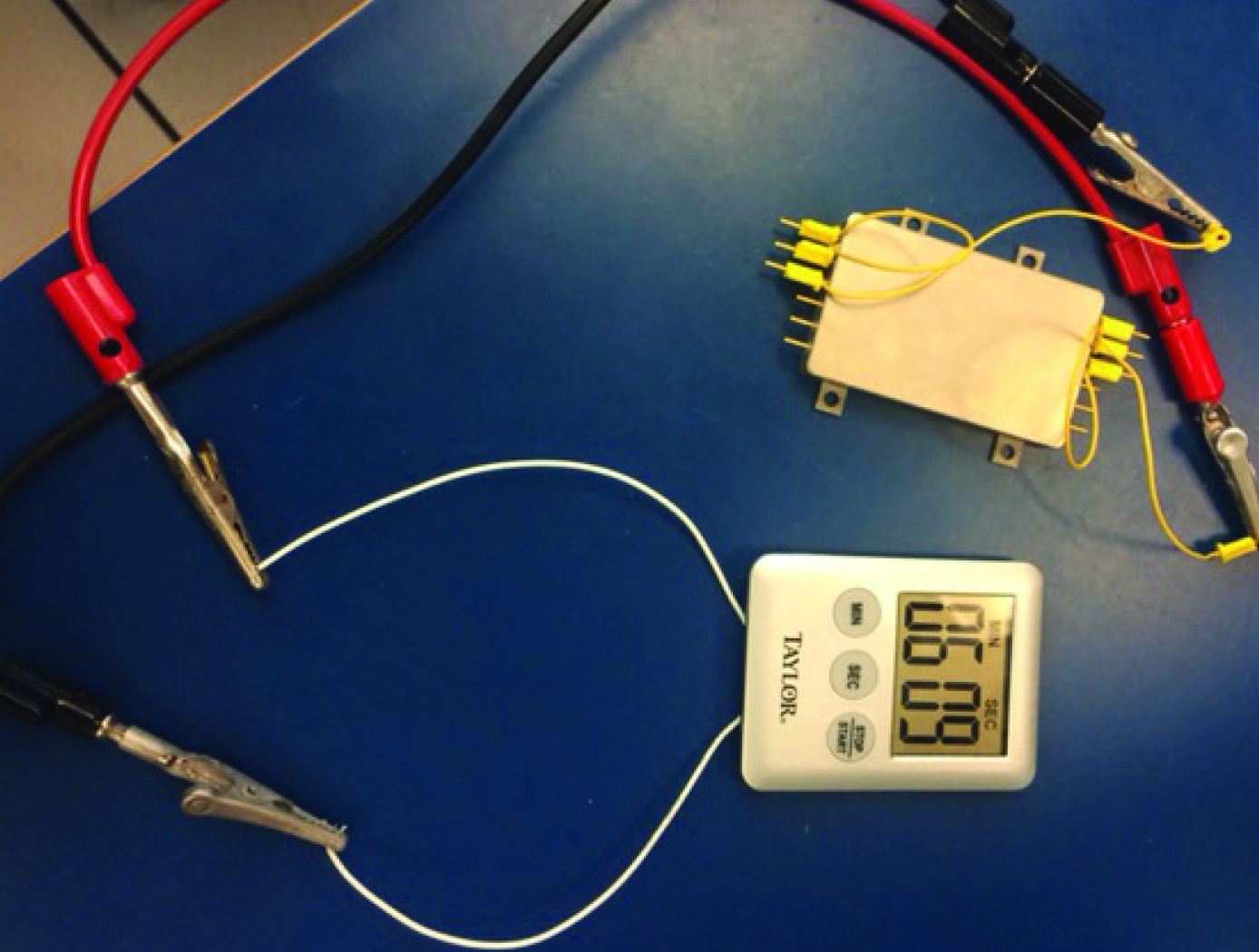
The technology can be used for dielectric tanks, by simply applying the sensors to the
tank surface (as pictured). Through certain techniques the technology can be applied
on metal tanks with no wires entering the tank from the outside.
Currently, there are more than 20,910 jet aircraft in service. This presents a large
market opportunity for retrofitting this technology onto existing airplane fuel tanks
Rapidly evolving aviation services are expected to spur worldwide requirement for
36,770 new jet aircraft by 2033. This presents a growing market for new installations.
Power Generation and Storage
Novel, Solid-State Hybrid Ultracapacitor Battery
The subject technology is an extension of closely related, solid-state ultracapacitor innovations by the same team of inventors. The primary distinction for this specific technology is the addition of co-dopants to affect the dielectric behavior of the barium titanatebased perovskite materials. These co-dopants include lanthanum and other rare earths as well as hydroxyl ions. The materials are processed at the nano scale, and are subjected to carefully designed thermal treatments as well.
The presence of the hydroxyl ions has been shown to provide several orders of magnitude increase in the capacitance of the dielectric material. Additionally, these high capacitance values are obtained at relatively low voltages found in current consumer and industrial electronics.
The capacitors tested to date are simple, single-layer devices. Ultimately, a range of manufacturing methods are possible for making commercial devices. Features of the technology enable manufacturing via traditional thick-film processing methods widely used in the capacitor industry, or via advanced printing methods for state-of-the-art printed electronics.
Future efforts will be made to advance the manufacturing and packaging processes to increase device energy density, including multilayer devices and packages
Mechanical and Fluid Systems

Modified Tuned Liquid Column Damper
When waves move a floating wind turbine, they drive fluid motion inside the MTLCD. This forces air in the vertical tanks through an orifice, increasing pressure much like a spring. As the air discharges, the fluid’s motion is damped and energy is dissipated. The MTLCD also incorporates added damping elements, such as an orifice or variable-aperture reciprocating reed valve, that create resistance to air flow, further controlling fluid motion and dissipating energy.
By integrating these modifications, the MTLCD is easily tuned to the platform’s motions, reducing dependency on platform geometry. Eliminating damping elements from the fluid removes the need for marine-grade hardware, reducing system costs. The MTLCD can also be integrated into existing ballast tanks, maximizing space efficiency with minimal added parts.
While initially developed for NASA’s Floating Wind Turbine Development project, this invention can support vibration mitigation applications across multiple industries, such as infrastructure, maritime systems, and aerospace. By enabling precise tuning of dynamic response characteristics, the MTLCD offers a compact solution for platforms requiring vibration suppression. The technology has completed preliminary design and simulation, is at a TRL 3 (proof-of-concept), and is available for patent licensing.
environment

Advanced Supercritical Water Oxidation Reactor
NASA's Supercritical Water Oxidation - Flame Piloted Vortex (SCWO-FPV) Reactor implements a unique design where heating is primarily supplied by the energetics of the waste stream through the control of a hydrothermal flame in the core of the reactor with the injection of fuel and oxidizer. Once the hydrothermal flame is initiated and stabilized, an outer-core "wash" stream, consisting primarily of water, is injected near the walls at the base of the reactor. This "wash" stream maintains subcritical conditions at the reactor walls, while also dissolving and/or flushing from the reactor any precipitate and non-soluble inorganic materials generated from the supercritical reactor core. Mixing between the core region and the outer subcritical flow region is largely eliminated due to the great differences in density and viscosity. The flow configuration is further stabilized by the generation of a vortex using internal structures on the inside of the reactor wall. An aspirator assembly is positioned at the top of the supercritical core region to extract treated water and un-extracted material is recirculated through the reactor. The rate and amount of aspiration will be determined by product monitoring and will depend on waste stream content and overall operating conditions. Key aspects of the technology have been demonstrated and a prototype reactor is under development.
Optics

Portable Integrated Fourier Ptychographic Microscope
NASA’s integrated, portable FPM device combines advanced optical microscopy with AI in a compact form factor. At its core, the system uses a Raspberry Pi camera module equipped with an 8-megapixel sensor and a 3-mm focal-length lens, achieving approximately 1.5× magnification. Illumination is provided by a Unicorn HAT HD LED array positioned 65mm below the sample stage, creating a synthetic numerical aperture of 0.55. All these components are controlled by an NVIDIA Jetson Nano board, which serves as the system's embedded AI computing platform. NASA’s portable FPM device can be integrated with a microfluidic system for sub-micron imaging of liquid samples.
In addition to its portability, what sets NASA’s integrated FPM device apart is its integration of deep learning capabilities. The invention has two modes – normal mode and deep learning mode. In its normal mode, the system captures data and performs intensity and 3D phase analysis using traditional FPM methods. The deep learning mode enhances this base functionality by employing neural networks for image reconstruction and system optimization. The AI system automatically detects when samples are out of focus and can either mechanically or digitally adjust to the correct focal plane. To achieve near real-time monitoring, deep learning models significantly reduce data acquisition time by selectively using only a portion of the LED array and provide fast reconstruction capabilities leveraging training on specific sample types.
While originally designed for imaging biosignature motility in liquid samples for spaceflight applications, this NASA innovation can image many different types of samples, and is not limited to biological specimens. The ability to operate this system in the field further broadens use-cases.

