Search
Sensors

A Generalized Ultrasonic Inspection Method for Batteries
The generalized ultrasonic inspection method harnesses piezoelectric transducers and ultrasonic resonance spectroscopy to detect sub-500-micron defects in batteries. By analyzing the resonance behavior of high-frequency sound waves and employing novel data processing techniques, subtle structural changes in batteries can be identified. Two hardware setups were developed: one employing direct transducer contact and another utilizing ultrasonic measurements through a captured water column. Both configurations incorporate a scanning technique that captures spatial degradation data – rather than a single point measurement – enabling structural insights even in layers too thin for time-domain c-scan resolution.
Processing of the data includes converting the measurements and reference time domain signals to the frequency domain, then normalizing the measurement signal in the frequency domain to determine the frequency dependent reflection coefficient. As a result, resonance behavior between the test specimen and apparatus can be isolated. This resonance-based approach is ideal for delicate materials unsuitable for high-powered laser excitation or full immersion testing, and the associated data-analysis allows the battery defects to be detected more efficiently.
This NASA invention offers significant potential for highly sensitive, nondestructive enhancements of battery safety and quality control in industries such as automotive, aerospace, additive manufacturing, and composites.
Manufacturing
X-Ray Crack Detectability
NASAs software technology uses an Image Quality Indicator (IQI)-based model that can predict whether cracks of a certain size can be detected, as well as a model that can provide appropriate conditions to optimize x-ray crack detection setup. Because this modeling software can predict minimum crack sizes that can be detected by a particular X-ray radiography testing setup, users can test various setups until the desired crack detection capabilities are achieved (predicted) by the modeling system.
These flaw size parameter models use a set of measured inputs, including thickness sensitivity, detector modulation transfer function, detector signal response function, and other setup geometry parameters, to predict the minimum crack sizes detectable by the testing setup and X-ray angle limits for detecting such flaws.
Current X-ray methods provide adequate control for detection of volumetric flaws but do not provide a high probability of detection (POD), and crack detection sensitivity cannot be verified for reliable detection. This results in reduced confidence in terms of crack detection. Given that these cracks, if undetected, can cause catastrophic failure in various systems (e.g., pressure vessels, etc.), verifying that X-ray radiography systems used for NDE can detect such cracks is of the utmost importance in many applications.
manufacturing
System for In-situ Defect Detection in Composites During Cure
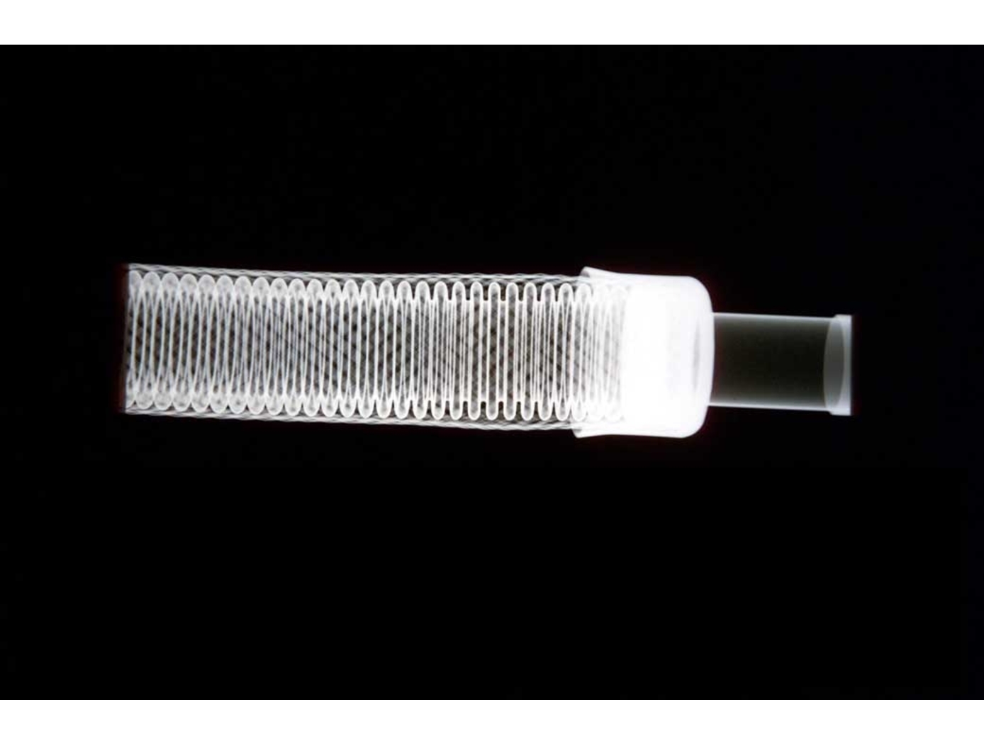
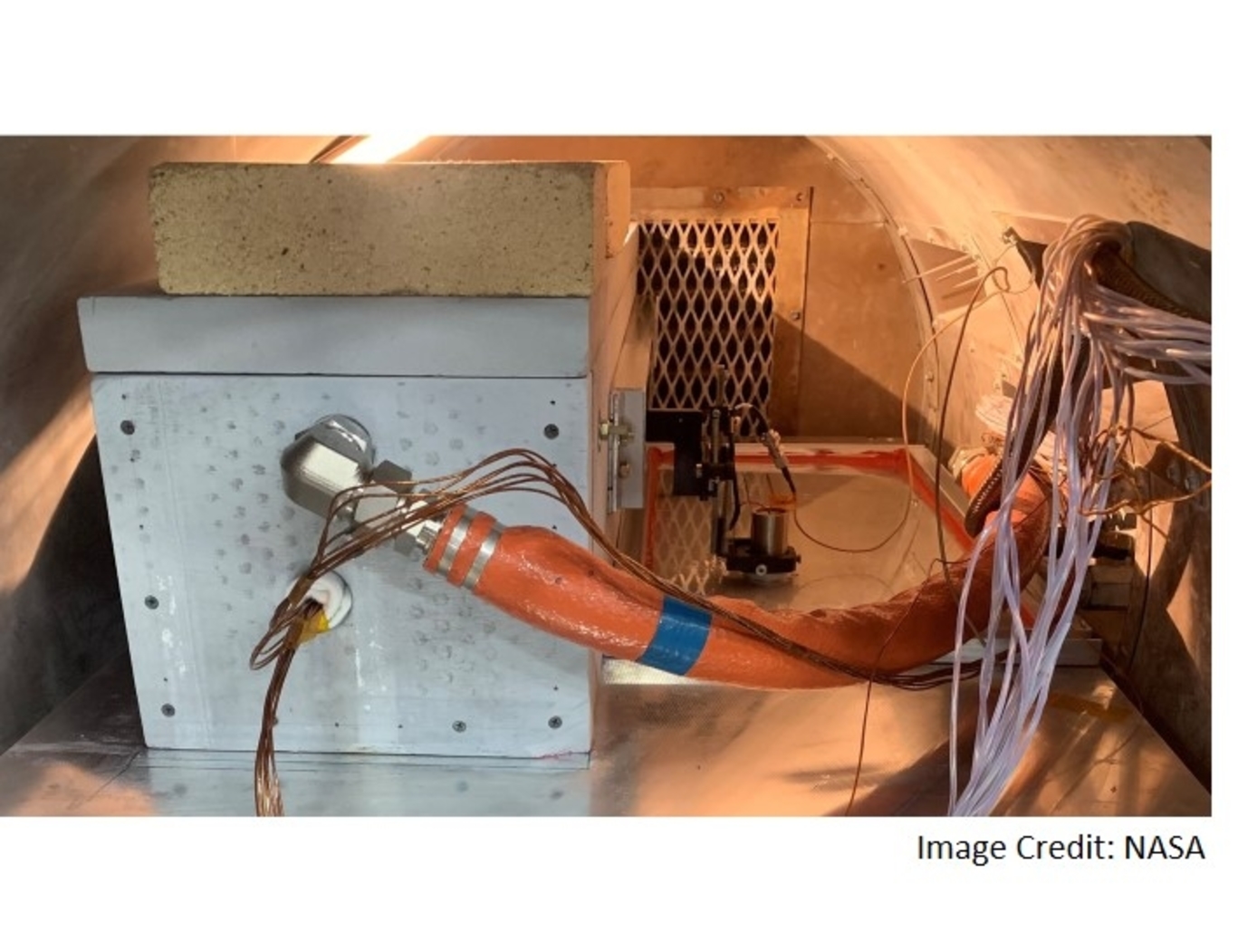
NASA's System for In-situ Defect (e.g., porosity, fiber waviness) Detection in Composites During Cure consists of an ultrasonic portable automated C-Scan system with an attached ultrasonic contact probe. This scanner is placed inside of an insulated vessel that protects the temperature-sensitive components of the scanner. A liquid nitrogen cooling systems keeps the interior of the vessel below 38°C. A motorized X-Y raster scanner is mounted inside an unsealed cooling container made of porous insulation boards with a cantilever scanning arm protruding out of the cooling container through a slot. The cooling container that houses the X-Y raster scanner is periodically cooled using a liquid nitrogen (LN2) delivery system. Flexible bellows in the slot opening of the box minimize heat transfer between the box and the external autoclave environment. The box and scanning arm are located on a precision cast tool plate. A thin layer of ultrasonic couplant is placed between the transducer and the tool plate. The composite parts are vacuum bagged on the other side of the tool plate and inspected. The scanning system inside of the vessel is connected to the controller outside of the autoclave. The system can provide A-scan, B-scan, and C-scan images of the composite panel at multiple times during the cure process.
The in-situ system provides higher resolution data to find, characterize, and track defects during cure better than other cure monitoring techniques. In addition, this system also shows the through-thickness location of any composite manufacturing defects during cure with real-time localization and tracking. This has been demonstrated for both intentionally introduced porosity (i.e., trapped during layup) as well processing induced porosity (e.g., resulting from uneven pressure distribution on a part). The technology can be used as a non-destructive evaluation system when making composite parts in in an oven or an autoclave, including thermosets, thermoplastics, composite laminates, high-temperature resins, and ceramics.
Materials and Coatings

Waveguide-based Dielectric and Magnetic Property Measurement
This NASA invention utilizes a simple waveguide-based measurement system to determine the complex dielectric permittivity and magnetic permeability of arbitrary-shaped planetary rock samples. The system operates at L-band frequencies (~1 GHz) and can be extended to P- and S-bands for broader applications. The approach involves placing an arbitrarily-shaped sample inside an open-ended waveguide excited by a coaxial probe, measuring the scattering parameters, and extracting dielectric and magnetic properties through computational modeling and optimization techniques.
A key aspect of this system is its ability to handle non-uniform and irregularly shaped rock samples, enabling the measurement of real-world planetary materials without requiring extensive sample preparation. The methodology includes calibration in an anechoic chamber, computational modeling, and iterative refinement of measured vs. simulated scattering parameters to extract the material properties.
Future advancements will involve expanding measurements to different frequency bands, refining computational models using artificial intelligence, and automatically rotating samples within the waveguide to obtain multiple directional measurements (enhancing precision while reducing test time).
This NASA innovation has been successfully applied to two Martian meteorite samples, yielding values of dielectric permittivity and permeability relevant for Mars radar applications. The system will further be leveraged to build an expansive database of the dielectric properties of planetary soils and rocks to improve radar-based mapping (e.g., subsurface mapping) missions. The invention could also be applied for the non-destructive screening of a variety of samples using radio waves, including biological samples for medical purposes, additive manufacturing feedstock or finished parts, and mining-related rock samples to test for impurities or resources of interest. This NASA invention is at technology readiness level (TRL) 5 (component and/or breadboard validation in relevant environment) and is available for patent licensing.

