Search
information technology and software

A Method For Developing And Maintaining Evolving Systems With Software Product Lines
The idea of a software product line has been developed that views software products that are substantially similar, or which have substantially similar content, as being different products in a line of products that the organization develops. For example, flight software for different missions can be viewed as a line of products that fulfills this purpose, with many of the products having similarities, or in extreme cases being very similar with a few specializations.
This method expands this view further and sees an evolving system, one that will likely run for a long period of time, and which must have corrections, enhancements and changes made to it over a period of time, as essentially exhibiting a product line. More specifically, different versions or releases of the system are viewed as different 'products' that are substantially similar. This method opens a new field of developing a complex system that is likely to involve many interacting components for development as a product line, which can be developed with state-of-the-art software engineering techniques.
mechanical and fluid systems

Compact Vibration Damper
Structural vibrations frequently need to be damped to prevent damage to a structure. To accomplish this, a standard linear damper or elastomeric-suspended masses are used. The problem associated with a linear damper is the space required for its construction. For example, if the damper's piston is capable of three inches of movement in either direction, the connecting shaft and cylinder each need to be six inches long. Assuming infinitesimally thin walls, connections, and piston head, the linear damper is at least 12 inches long to achieve +/-3 inches of movement. Typical components require 18+ inches of linear space. Further, tuning this type of damper typically involves fluid changes, which can be tedious and messy. Masses suspended by elastomeric connections enable even less range of motion than linear dampers.
The NASA invention is for a compact and easily tunable structural vibration damper. The damper includes a rigid base with a slider mass for linear movement. Springs coupled to the mass compress in response to the linear movement along either of two opposing directions. A rack-and-pinion gear coupled to the mass converts the linear movement to a corresponding rotational movement. A rotary damper coupled to the converter damps the rotational movement. To achieve +/- 3 inches of movement, this design requires slightly more than six inches of space.
information technology and software
Inductive Monitoring System
The Inductive Monitoring System (IMS) software provides a method of building an efficient system health monitoring software module by examining data covering the range of nominal system behavior in advance and using parameters derived from that data for the monitoring task. This software module also has the capability to adapt to the specific system being monitored by augmenting its monitoring database with initially suspect system parameter sets encountered during monitoring operations, which are later verified as nominal. While the system is offline, IMS learns nominal system behavior from archived system data sets collected from the monitored system or from accurate simulations of the system. This training phase automatically builds a model of nominal operations, and stores it in a knowledge base. The basic data structure of the IMS software algorithm is a vector of parameter values. Each vector is an ordered list of parameters collected from the monitored system by a data acquisition process. IMS then processes select data sets by formatting the data into a predefined vector format and building a knowledge base containing clusters of related value ranges for the vector parameters. In real time, IMS then monitors and displays information on the degree of deviation from nominal performance. The values collected from the monitored system for a given vector are compared to the clusters in the knowledge base. If all the values fall into or near the parameter ranges defined by one of these clusters, it is assumed to be nominal data since it matches previously observed nominal behavior. The IMS knowledge base can also be used for offline analysis of archived data.
mechanical and fluid systems
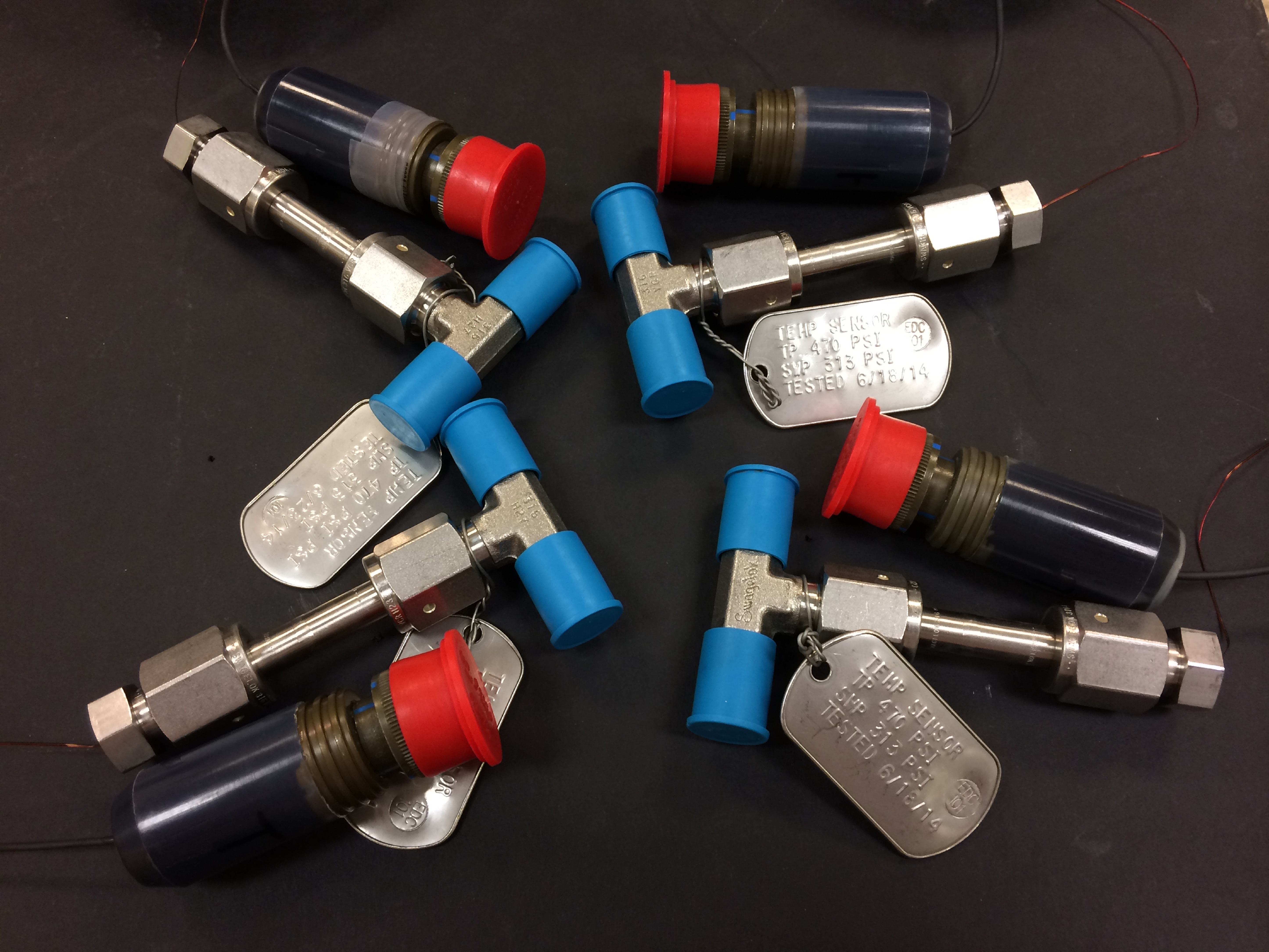
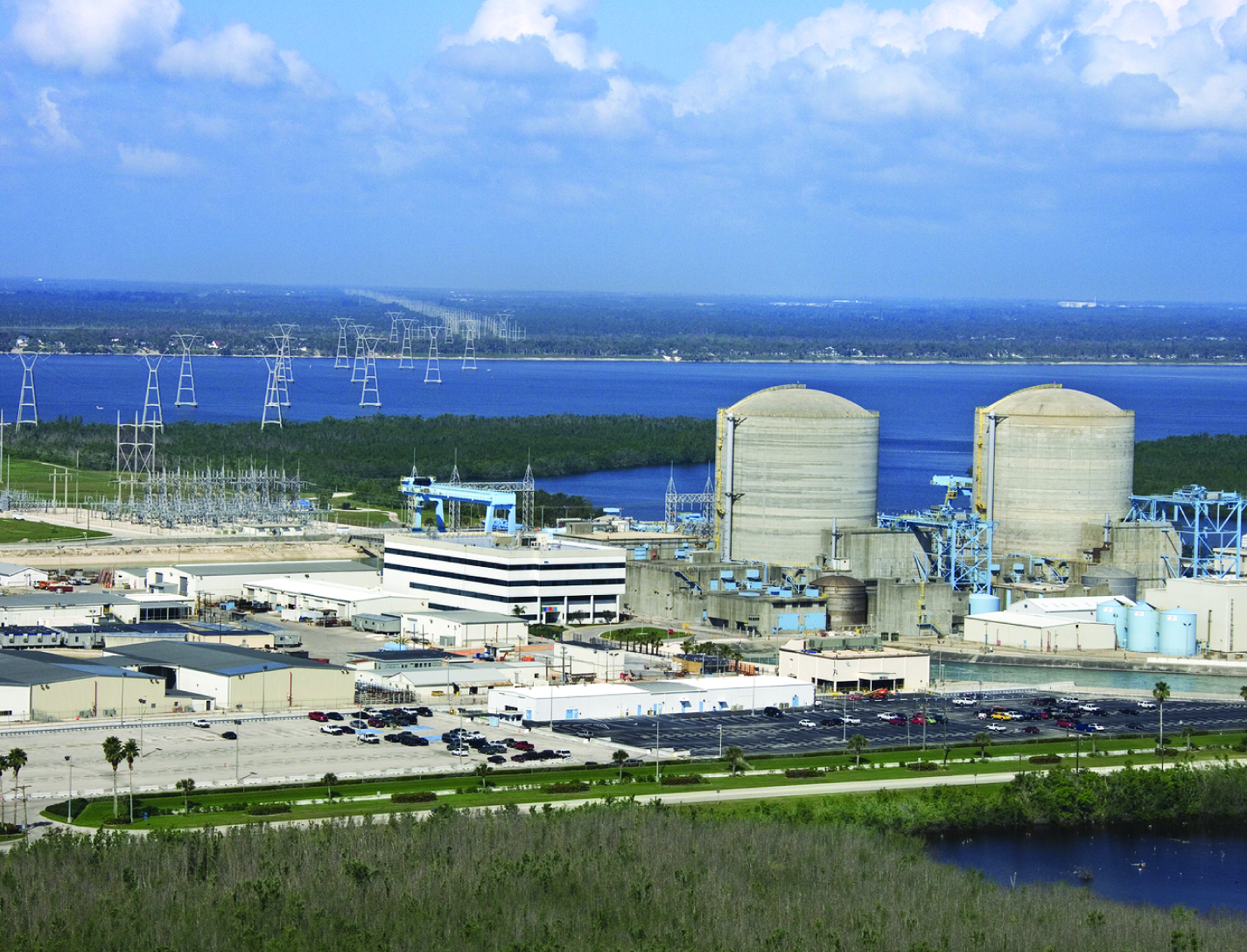
Feedthrough for Severe Environments and Temperatures
Space and ground launch support related hardware often operate under extreme pressure, temperature, and corrosive conditions. When dealing with this type of equipment, it is frequently necessary to run wiring, tubes, or fibers through a barrier separating one process from another with one or both operating in extreme environments. Feedthroughs used to route the wiring, tubes, or fibers through these barriers must meet stringent sealing and leak tightness requirements.
This affordable NASA feedthrough meets or exceeds all sealing and leak requirements utilizing easy-to-assemble commercial-off-the-shelf hardware with no special tooling. The feedthrough is a fully reconfigurable design; however, it can also be produced as a permanent device. Thermal cycling and helium mass spectrometer leak testing under extreme conditions of full cryogenic temperatures and high vacuum have proven the sealing capability of this feedthrough with or without potting (epoxy fill) on the ends. Packing material disks used in the construction of the device can be replaced as needed for rebuilding a given feedthrough for another job or a different set of feeds if potting is not used for the original feedthrough build. (Potting on one or both sides of the sleeve provides double or triple leak sealing protection). Variable Compression Ratio (VCR) connectors were adapted for the pressure seal on the feedthrough; however, any commercial connector can be similarly adapted. The design can easily be scaled up to larger (2" diameter) and even very large (12" or more) sizes.
mechanical and fluid systems
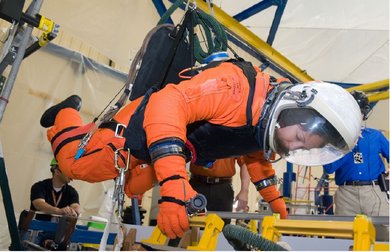
Full-Size Reduced Gravity Simulator For Humans, Robots, and Test Objects
The Active Response Gravity Offload System (ARGOS) provides a simulated reduced gravity environment that responds to human-imparted forces. System capabilities range from full gravity to microgravity. The system utilizes input/feedback sensors, fast-response motor controllers, and custom-developed software algorithms to provide a constant force offload that simulates reduced gravity.
The ARGOS system attaches to a human subject in a gimbal and/or harness through a cable. The system then maintains a constant offload of a portion of the subjects weight through the cable to simulate reduced gravity. The system supports movements in all 3 dimensions consistent with the selected gravity level. Front/back and left/right movements are supported via a trolley on an overhead runway and bridge drive system, and up/down movements are supported via a precisely positioned cable. The system runs at a very high cycle rate, and constantly receives feedback to ensure the human subjects safety.
Electrical and Electronics
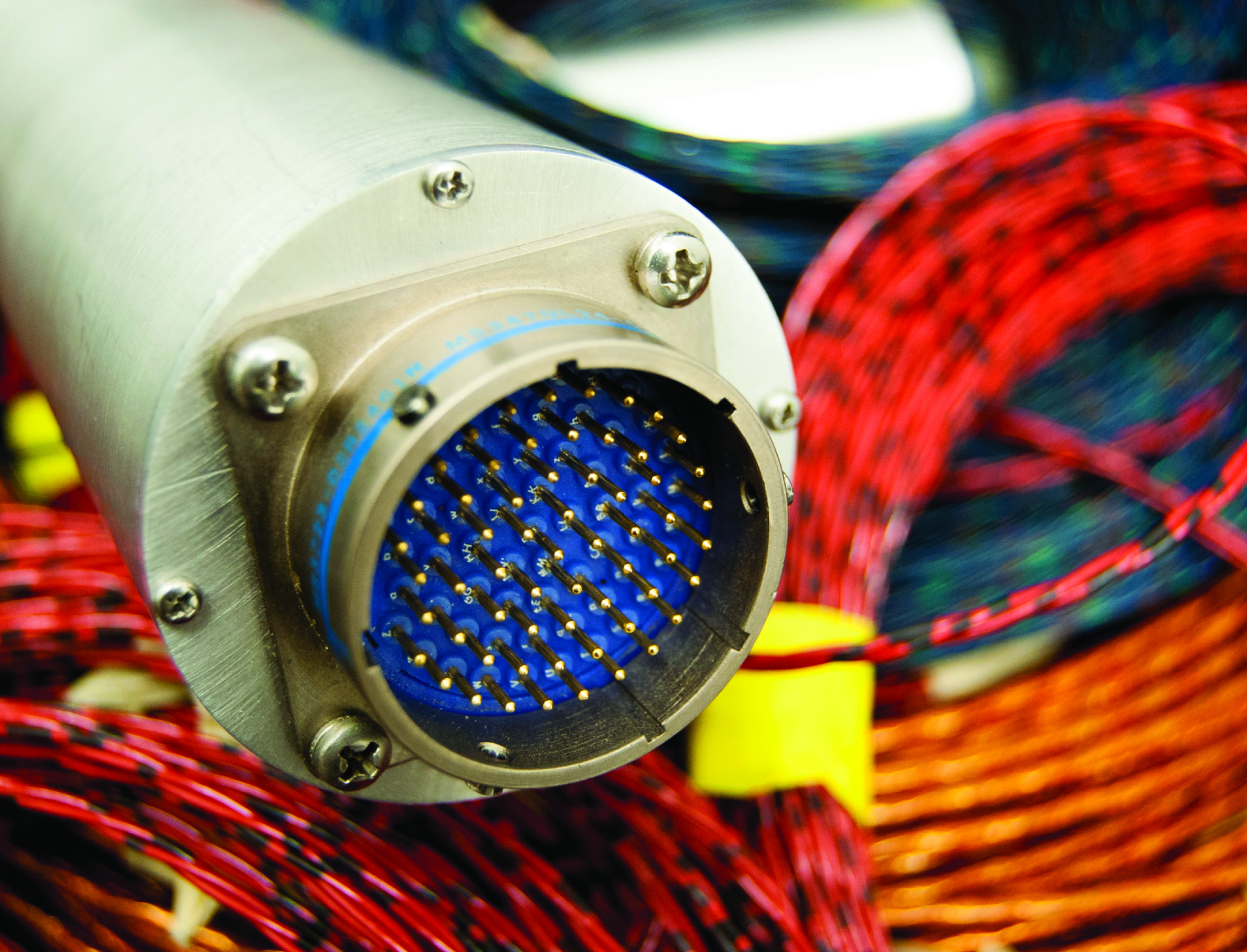
In Situ Wire Damage Detection and Rerouting System
The tester was designed to monitor electrical faults in either online or offline modes of operation. In the online mode, wires are monitored without disturbing their normal operation. A cable can be monitored several times per second in the offline mode, and once per second in the online mode. The online cable fault locator not only detects the occurrence of a fault, but also determines the type of fault (short/open/intermittent) and the location of the fault. This enables the detection of intermittent faults that can be repaired before they become serious problems. Since intermittent faults occur mainly during operations, a built-in memory device stores all relevant fault data. This data can be displayed in real time or retrieved later so maintenance and repairs can be completed without spending countless hours attempting to pinpoint the source of the problem.
Hardware and algorithms have also been developed to safely, efficiently, and autonomously transfer electrical power and data connectivity from an identified damaged/defective wire in a cable to an alternate wire path. This portion of the system consists of master and slave units that provide the diagnostic and rerouting capabilities. A test pulse generated by the master unit is sent down an active wire being monitored by the slave unit. When the slave unit detects the test pulse, it routes the pulse back to the master unit through a communication wire. When the master unit determines that a test pulse is not being returned, it designates that wire as faulty and reroutes the circuit to a spare wire.
Materials and Coatings
Low-Temperature Oxidation/
Reduction Catalysts
The low-temperature oxidation catalyst technology employs a novel catalyst formulation, termed platinized tin oxide (Pt/SnOx). The catalysts can be used on silica gel and cordierite catalyst supports, and the latest developments provide sprayable formulations for use on a range of support types and shapes. Originally developed for removal of CO, the catalyst has also proven effective for removal of formaldehyde and other lightweight hydrocarbons.
NASA researchers have also extended the capability to include reduction of NOx as well as developed advanced chemistries that stabilized the catalyst for automotive catalytic converters via the engineered addition of other functional components. These catalyst formulations operate at elevated temperatures and have performed above the EPA exhaust standards for well beyond 25,000 miles. In addition, the catalyst can be used in diesel engines because of its ability to operate over an increased temperature range.
For use as a gas sensor, the technology takes advantage of the exothermic nature of the catalytic reaction to detect formaldehyde, CO, or hydrocarbons, with the heat being produced proportional to the amount of analyte present.
Manufacturing
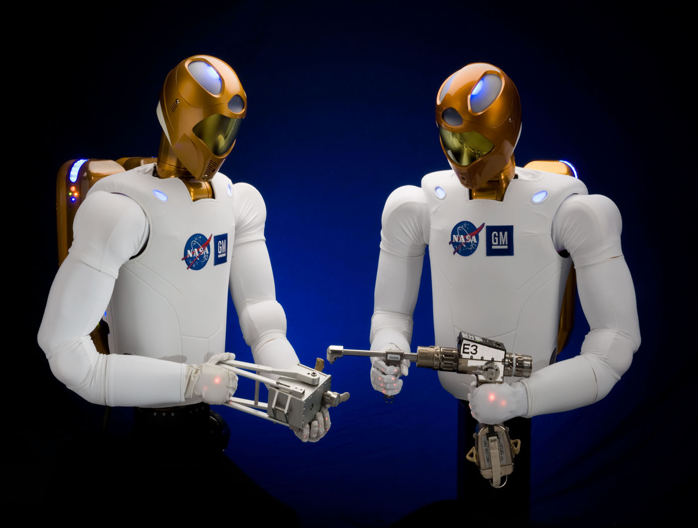
Robonaut 2: Industrial Opportunities
NASA, GM, and Oceaneering approached the development of R2 from a dual use environment for both space and terrestrial application. NASA needed an astronaut assistant able to function in space and GM was looking for a robot that could function in an industrial setting. With this in mind, R2 was made with many capabilities that offer an enormous advantage in industrial environments. For example, the robot has the ability to retool and vary its tasks. Rather than a product moving from station to station on a conveyor with dozens of specialized robots performing unique tasks, R2 can handle several assembly steps at a single station, thereby reducing manufacturing floor space requirements and the need for multiple robots for the same activities. The robot can also be used in scenarios where dangerous chemicals, biological, or even nuclear materials are part of the manufacturing process.
R2 uses stereovision to locate human teammates or tools and a navigation system. The robot was also designed with special torsional springs and position feedback to control fine motor movements in the hands and arms. R2's hands and arms sense weight and pressure and stop when they come in contact with someone or something. These force sensing capabilities make R2 safe to work side-by-side with people on an assembly line, assisting them in ergonomically challenging tasks or working independently.
This NASA Technology is available for your company to license and develop into a commercial product. NASA does not manufacture products for commercial sale.
sensors
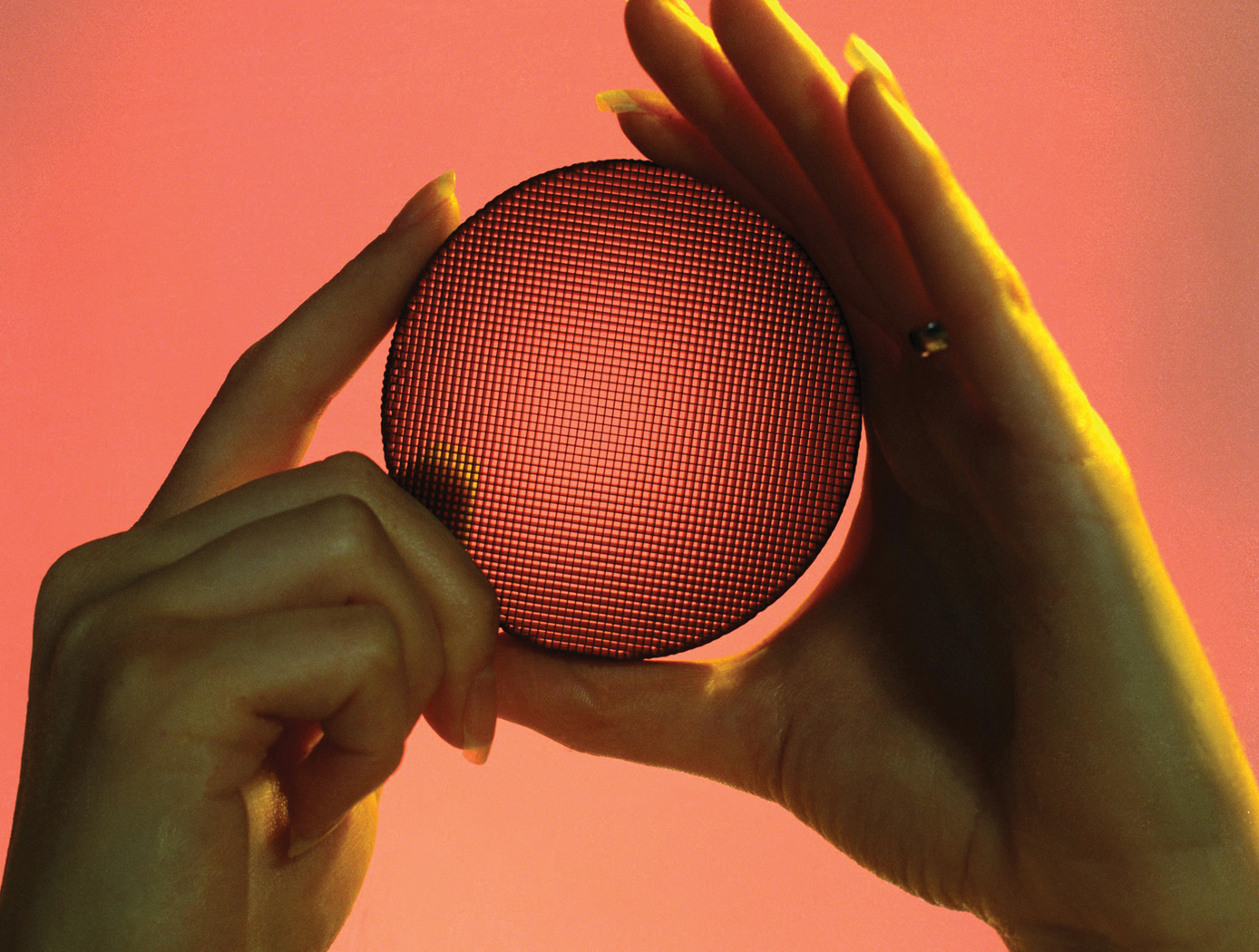
Low-Profile Wireless Sensor
The low-profile sensor is configured with a spiral electrical trace on flexible substrate. In typical inductor designs, the space between traces is designed to minimize parasitic conductance to reduce the impact of the capacitance to neighboring electronics. In the low-profile sensor, however, greater capacitance is desired to allow the operation of an inductor-capacitor circuit. This allows the traces to be closer together, decreasing the
overall size of the spiral trace.
The sensor receives a signal from the accompanying magnetic field data acquisition system. Once electrically active, the sensor produces its own harmonic magnetic field as the inductor stores and releases magnetic energy. The antenna of the measurement acquisition system is switched from a transmitting to a receiving mode to acquire the magnetic-field response of the sensor. The magnetic-field response attributes of frequency, amplitude, and bandwidth of the inductor correspond to the physical property states measured by the sensor. The received response is correlated to calibration data to determine the physical property measurement. When multiple sensors are inductively coupled, the data acquisition system needs to activate and read
only one sensor to obtain measurement data from all of them.
mechanical and fluid systems

High-Temperature Single Crystal Preloader
For extremely high-temperature sealing applications, Glenn researchers have devised novel methods for fabricating single-crystal preloaders. NASA's high-temperature preloaders consist of investment cast or machined parts that are fabricated in various configurations from single crystal superalloys. Machined preloaders include a variety of spring configurations, compressed axially or radially, fabricated from single crystal slabs. Before machining, the slabs are carefully oriented in a special goniometer using x-diffraction techniques. This helps to maintain proper crystal orientation relative to the machined part and the applied loads. For more complex geometry components which cannot be easily and economically machined, an investment casting approach would be used. Complex preloader geometries include wire coil springs of various configurations. These single crystal preloaders would be designed with the appropriate stiffness for the intended thermal barrier/seal application and placed underneath, or integrated within, the seal/barrier. At extrememly high temperature, the preload device keeps the seal/barrier mated against the opposing surface as the gap between the two surfaces changes, maintaining contact between surfaces and preventing convective heat transfer.

