Search
instrumentation

Projected Background-Oriented Schlieren Imaging
The Projected BOS imaging system developed at the NASA Langley Research Center provides a significant advancement over other BOS flow visualization techniques. Specifically, the present BOS imaging method removes the need for a physically patterned retroreflective background within the flow of interest and is therefore insensitive to the changing conditions due to the flow. For example, in a wind tunnel used for aerodynamics testing, there are vibrations and temperature changes that can affect the entire tunnel and anything inside it. Any patterned background within the wind tunnel will be subject to these changing conditions and those effects must be accounted for in the post-processing of the BOS image. This post-processing is not necessary in the Projected BOS process here.
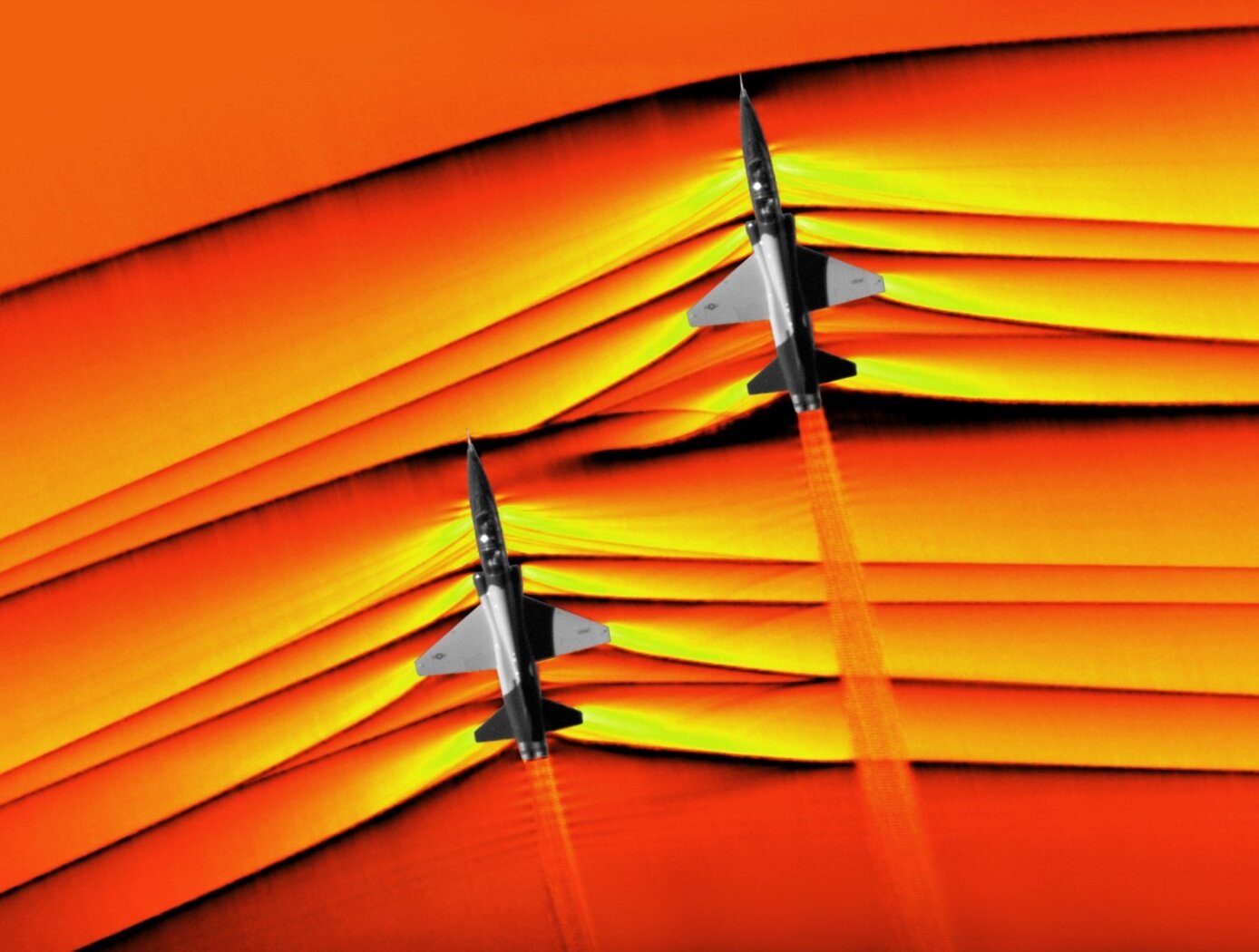
In the Projected BOS system, a pattern is projected onto a retroreflective background across the flow of interest (Figure 1). The imaged pattern in this configuration can be made physically (a pattern on a transparent slide) or can be digitally produced on an LCD screen. In this projection scheme, a reference image can be taken at the same time as the signal image, facilitating real-time BOS imaging and the pattern to be changed or optimized during the measurements. Thus far, the Projected BOS imaging technology has been proven to work by visualizing the air flow out of a compressed air canister taken with this new system (Figure 2).
Robotics Automation and Control

Robotic System for Infra-structure Reconnaissance
The robotic system is comprised of six main components: the orb that performs the reconnaissance, an orb injector housing that attaches to a piping network, a tether and reel subsystem that attaches to the back of the injector housing, a fluid injection subsystem that attaches toward the front of the injector housing, an external power and data subsystem, and associated control and monitoring software.
Usage of the system begins with an operator attaching the injector housing, with the orb stowed inside, to a flanged gate valve belonging to the piping network of concern. Requisite power, data, and fluid subsystems are attached, and the system is energized for usage. The orb is released via the tether and reel, and a controlled fluid force is imparted on the orb to help guide it along its mission. The tether supplies power and guidance to the orb, and relays real-time data back to the operator.
The orb’s interior features a modular plug-and-play architecture which may comprise COTS instrumentation for reconnaissance or investiga-tion, LIDAR, and inertial measuring and motion sensors. This instru-mentation could be used in combination with other sub-systems such as lighting, and core and sample retrieving mechanisms. These com-ponents are supported by other onboard devices such as a CPU, power source and controller, and data transmission encoders and multiplexers.
The Robotic System for Infrastructure Reconnaissance is at TRL 8 (actual system completed and "flight qualified" through test and demonstration), and is now available for licensing. Please note that NASA does not manufacture products itself for commercial sale.


