Search
instrumentation
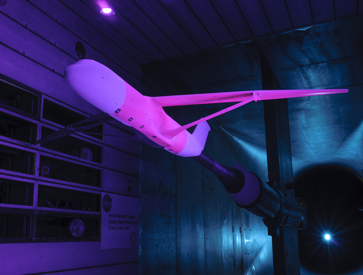
Calculation of Unsteady Aerodynamic Loads Using Fast-Response Pressure-Sensitive Paint (PSP)
Traditionally, unsteady pressure transducers have been the instrumentation of choice for investigating unsteady flow phenomena which can be time-consuming and expensive. The ability to measure and compute these flows has been a long-term challenge for aerospace vehicle designers and manufacturers. Results using only the pressure transducers are prone to inaccuracies, providing overly conservative load predictions in some cases and underestimating load predictions in other areas depending on the flow characteristics. NASA Ames has developed a new state-of-the-art method for measuring fluctuating aerodynamic-induced pressures on wind tunnel models using unsteady Pressure Sensitive Paint (uPSP). The technology couples recent advances in high-speed cameras, high-powered energy sources, and fast response pressure-sensitive paint. The unsteady pressure-sensitive paint (uPSP) technique has emerged as a powerful tool to measure flow, enabling time-resolved measurements of unsteady pressure fluctuations within a dense grid of spatial points on a wind tunnel model. The invention includes details surrounding uPSP processing. This technique enables time-resolved measurements of unsteady pressure fluctuations within a dense grid of spatial points representing the wind tunnel model. Since uPSP is applied by a spray gun, it is continuously distributed. With this approach, if the model geometry can be painted, viewed from a camera, and excited by a lamp source, uPSP data can be collected. Unsteady PSP (uPSP) has the ability to determine more accurate integrated unsteady loads.
manufacturing

Ultrasonic Stir Welding
Ultrasonic Stir Welding is a solid state stir welding process, meaning that the weld work piece does not melt during the welding process. The process uses a stir rod to stir the plasticized abutting surfaces of two pieces of metallic alloy that forms the weld joint. Heating is done using a specially designed induction coil. The control system has the capability to pulse the high-power ultrasonic (HPU) energy of the stir rod on and off at different rates from 1-second pulses to 60-millisecond pulses. This pulsing capability allows the stir rod to act as a mechanical device (moving and stirring plasticized nugget material) when the HPU energy is off, and allowing the energized stir rod to transfer HPU energy into the weld nugget (to reduce forces, increase stir rod life, etc.) when the HPU energy is on. The process can be used to join high-melting-temperature alloys such as titanium, Inconel, and steel.
materials and coatings
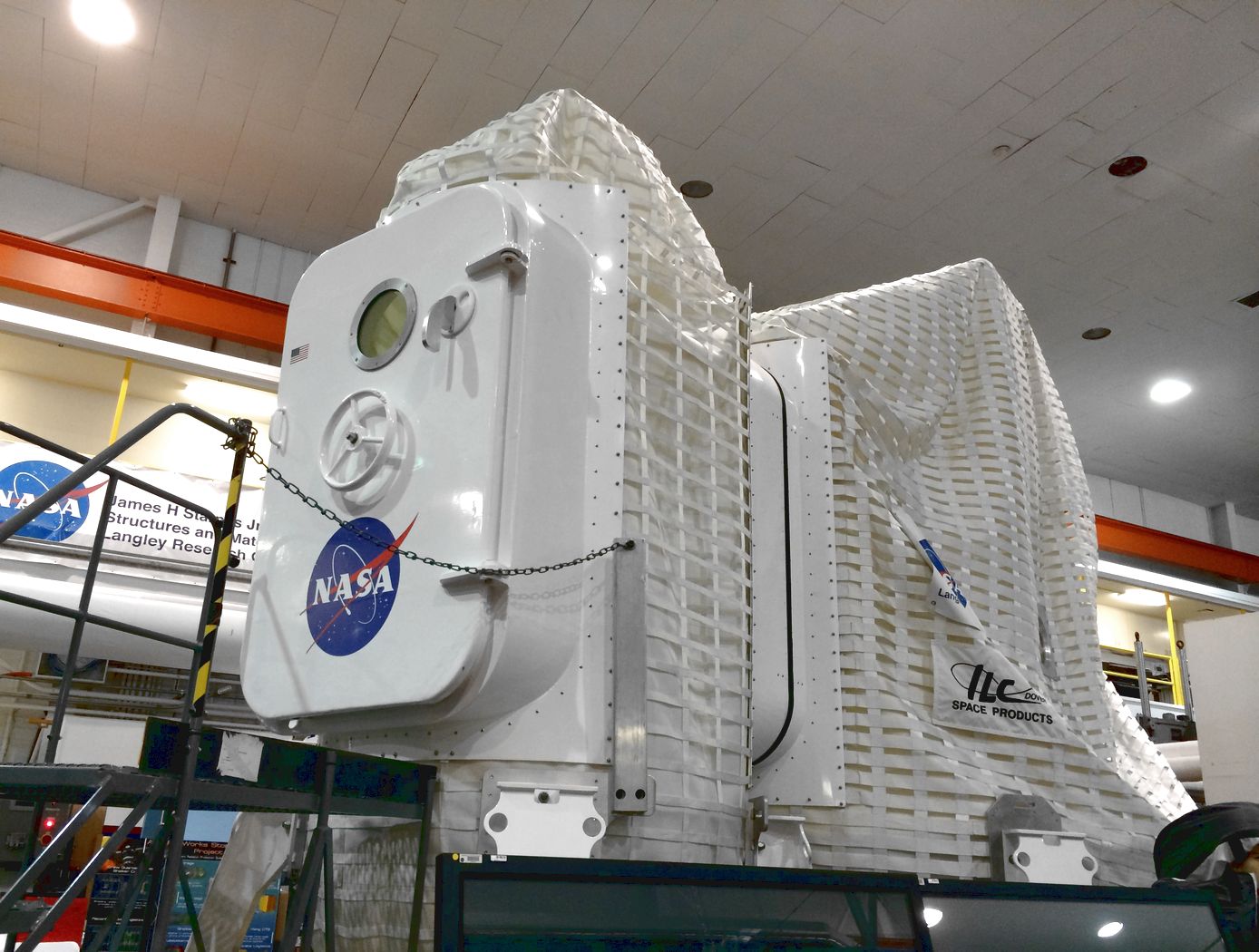
Multi-layered Self-healing Material System for Impact Mitigation
This innovation utilizes a tri-layered structure, comprised of solid plastic front and back layers sandwiching a viscous, reactive liquid middle layer. Combined, this system provides rapid self-healing following high velocity ballistic penetrations. Self-healing in the front and back layers occurs when the puncture event creates a melt state in the polymer materials and the materials melt elasticity snaps back and closes the hole. The viscous middle layer augments the self-healing properties of the other layers by flowing into the gap created by a ballistic puncture and concurrently solidifying due to the presence of oxygen. Thus, this innovation has two tiers of self-healing: a puncture-healing mechanism triggered by the projectile and a second mechanism triggered by the presence of oxygen.
Mechanical and Fluid Systems

Healable Carbon Fiber Reinforced Composites
A composite fabrication process cycle was developed from composite precursor materials developed at LaRC to fabricate composite laminates. The precursor material is a pre-impregnated unidirectional carbon fiber preform, or prepreg. In the pre-pregging process, the high strength, structural reinforcing carbon fiber is wetted by a solution containing a self-healing polymer. The resulting material is of aerospace quality and exhibits a significant decrease of internal damage following impacts tests (using ASTM D 7137 standard).
Mechanical and Fluid Systems
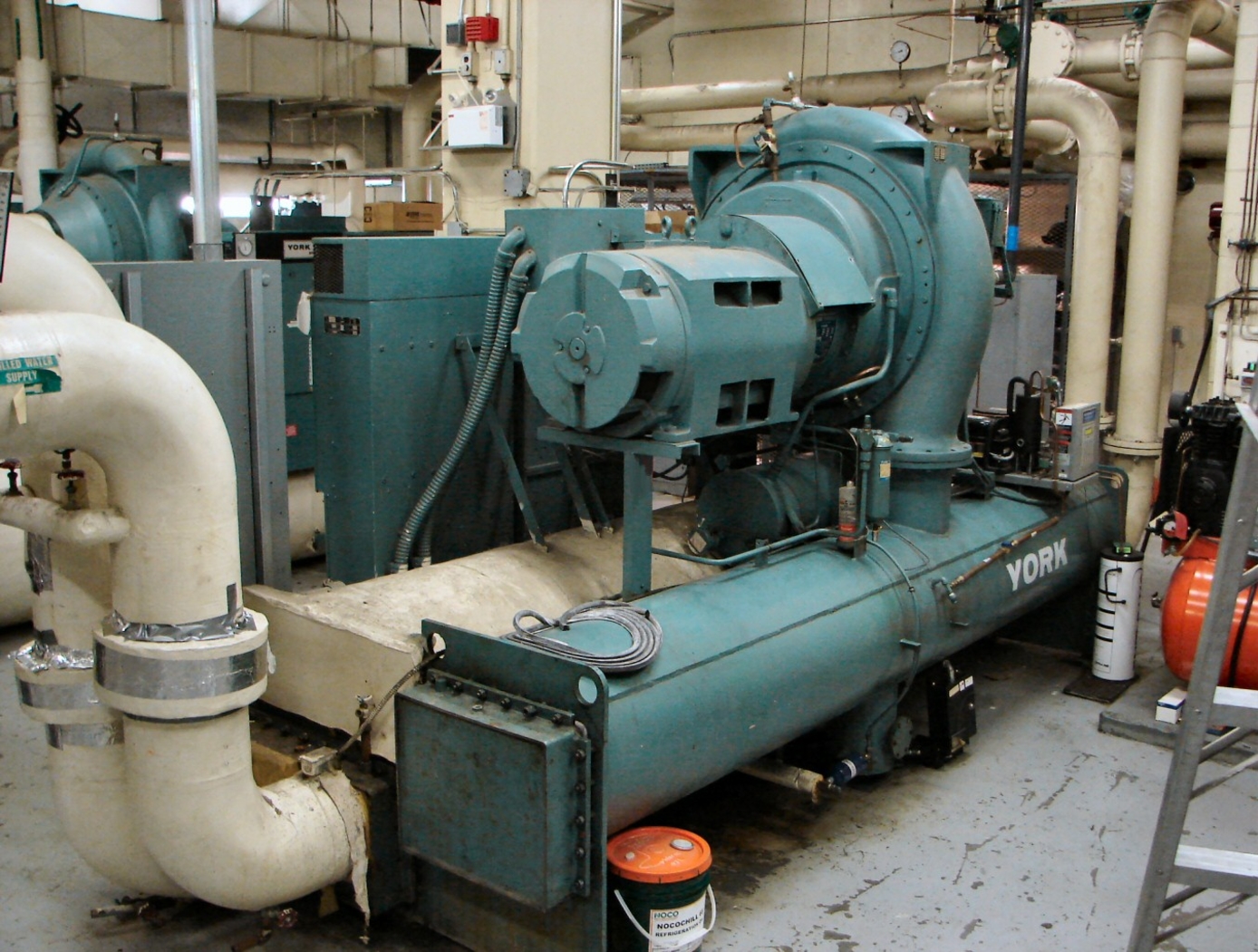
Variable-Aperture Reciprocating Reed (VARR) Valve
The VARR valve has been designed to provide a variable-size aperture that proportionately changes in relation to gas flow demand. When the pressure delta between two chambers is low, the effective aperture cross-sectional area is small, while at high delta pressure the effective aperture cross-sectional area is large. This variable aperture prevents overly restricted gas flow. As shown in the drawing below, gas flow through the VARR valve is not one way. Gas flow can traverse through the device in a back-and-forth reversing flow manner or be used in a single flow direction manner. The contour shapes and spacing can be set to create a linear delta pressure vs. flow rate or other pressure functions not enabled by current standard orifices. Also, the device can be tuned to operate as a flow meter over an extremely large flow range as compared to fixed-orifice meters. As a meter, the device is capable of matching or exceeding the turbine meter ratio of 150:1 without possessing the many mechanical failure modes associated with turbine bearings, blades, and friction, etc.
Power Generation and Storage

Isostatically Pressurized and Lightweight Cell Case for Solid-State Batteries
Battery cells are sealed inside a strong, flexible pouch which is placed inside a lightweight pressure vessel filled with inert working fluid (e.g., argon gas, silicone oil) that applies a low pressure evenly around the pouch, ensuring uniform compression and eliminating directional stress on the cell. This case maintains constant pressure throughout the battery’s life cycle to ensure consistent contact between solid components, which optimizes performance and minimizes damage. The pressure necessary in this design is much lower than that in uniaxial systems, which allows for a less heavy packaging system. This lightweight design and improved technique may show particular relevance on large scales (e.g., aerospace, automotive), where onboard load weight and longevity are priorities.
This isostatic battery case contributes to the SABERS 2.0 portfolio (LEW-TOPS-188), improving the state of the art for solid-state batteries. Currently at a TRL 4, the case is available to license independently or as part of the larger SABERS solid-state battery suite.
Mechanical and Fluid Systems
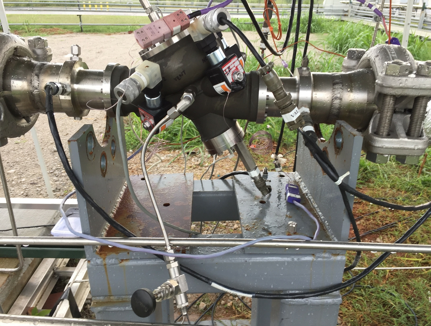
Cryogenic Hydraulically Actuated Isolation Valve
NASA's cryogenic isolation valve technology uses solenoid valves powered by direct current (DC) electrical energy to control and redirect the energy stored in the upstream line pressure. Powering the solenoid valves only requires a DC power source capable of supplying 22 watts that can be distributed and controlled in an on/off manner. By achieving actuation using only upstream line pressure and a 22-watt DC power source, many additional support systems that are required for electromechanical and pneumatic actuation are eliminated. This reduction of parts results in several benefits, including reduced footprint, weight, and potential cost of the valve in addition to lower energy consumption.
NASA fabricated several operational prototype valves using this technology for a rocket company. The table below shows the results of tests performed on these valves under cryogenic conditions. Please contact the NASA MSFC Technology Transfer Office for additional information.
mechanical and fluid systems
Floating Piston Valve
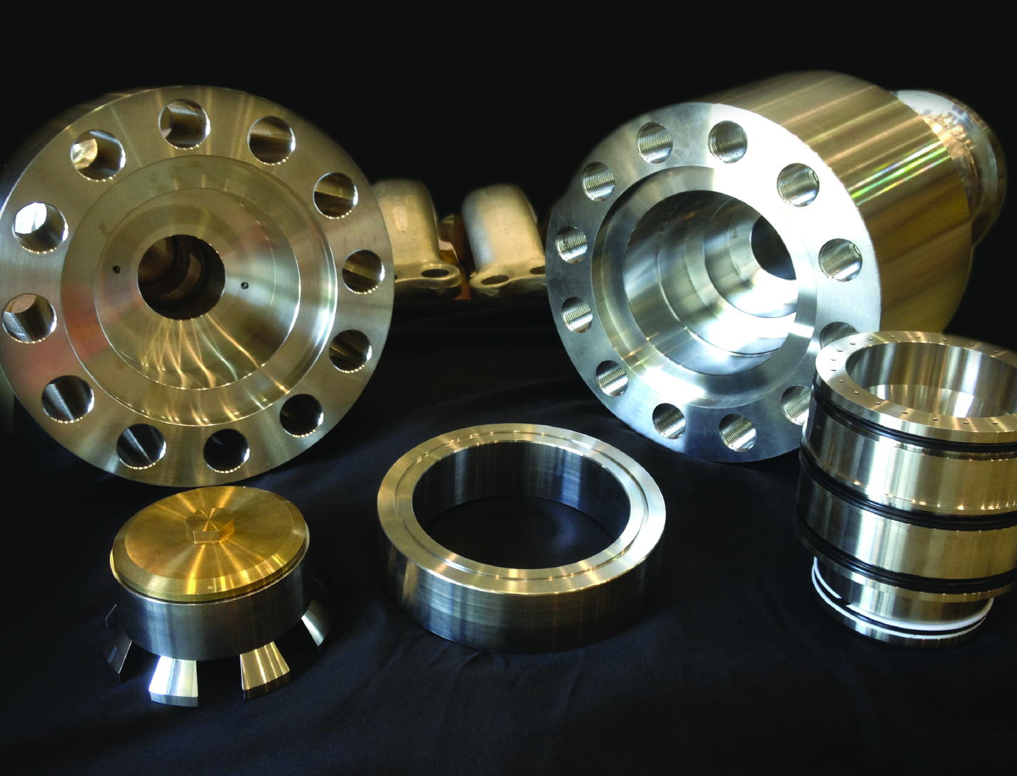
Instead of looking to improve current valve designs, a new type of valve was conceived that not only addresses recurring failures but could operate at very high pressures and flow rates, while maintaining high reliability and longevity. The valve design is applicable for pressures ranging from 15-15,000+ psi, and incorporates a floating piston design, used for controlling a flow of a pressurized working fluid.
The balanced, floating piston valve design has a wide range of potential applications in all sizes and pressure ranges. The extremely simple design and few parts makes the design inherently reliable, simple to manufacture, and easy to maintain. The valve concept works with soft or hard metal seats, and the closing force is easily adjustable so that any closing force desired can be created. The fact that no adjustment is required in the design, ensures valve performance throughout valve life and operation.
This valve has many unique features and design advantages over conventional valve concepts:
- The largest advantage is the elimination of the valve stem and any conventional actuator, reduces physical size and cost.
- It is constructed with only 5 parts.
- It eliminates the need for many seals, which reduces failure, downtime and maintenance while increasing reliability and seat life.
- The flow path is always axially and radially symmetric, eliminating almost all of the flow induced thrust loads - even during transition from closed to open.
Mechanical and Fluid Systems
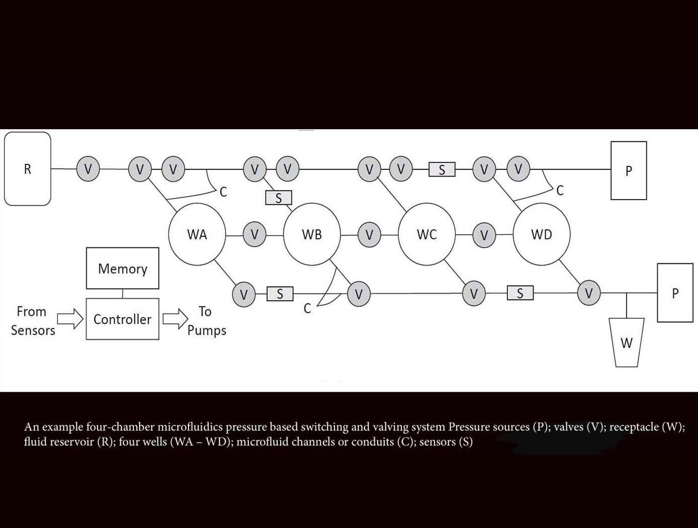
Microfluidics Pressure-Based Switching and Valving Array
The innovative technology from Ames acts as a microfluidics switch array, using combinations of pressure and flow conditions to achieve specific logic states that determine the sequences of sample movement between microfluidic wells. This advancement will enable automation of complex laboratory techniques not possible with earlier microfluidics technologies that are designed to follow predetermined flow paths and well targets. This novel method also enables autonomous operations including changing the flow paths and targeting well configurations in situ based on measured data decision parameters. This microfluidic system can be reconfigured for use in various experimental applications, requiring only an adjustment of the programmed pressure sequencing, reducing the need for custom design and development for each new application. For example, this technology could provide the ability to selectively constrain or move biological specimens in the experimental wells, allowing evolutionary studies of model organisms in response to various stressors, evaluation of different growth conditions on biological production of antibodies or other small molecule therapeutics, among other potential applications. Likewise, this platform can be used to foster time-dependent, step-wise, chemical reactions, which could be used for novel chemical processes or in situ resource utilization.
Mechanical and Fluid Systems

Modified Tuned Liquid Column Damper
When waves move a floating wind turbine, they drive fluid motion inside the MTLCD. This forces air in the vertical tanks through an orifice, increasing pressure much like a spring. As the air discharges, the fluid’s motion is damped and energy is dissipated. The MTLCD also incorporates added damping elements, such as an orifice or variable-aperture reciprocating reed valve, that create resistance to air flow, further controlling fluid motion and dissipating energy.
By integrating these modifications, the MTLCD is easily tuned to the platform’s motions, reducing dependency on platform geometry. Eliminating damping elements from the fluid removes the need for marine-grade hardware, reducing system costs. The MTLCD can also be integrated into existing ballast tanks, maximizing space efficiency with minimal added parts.
While initially developed for NASA’s Floating Wind Turbine Development project, this invention can support vibration mitigation applications across multiple industries, such as infrastructure, maritime systems, and aerospace. By enabling precise tuning of dynamic response characteristics, the MTLCD offers a compact solution for platforms requiring vibration suppression. The technology has completed preliminary design and simulation, is at a TRL 3 (proof-of-concept), and is available for patent licensing.

