Search
Sensors

A Generalized Ultrasonic Inspection Method for Batteries
The generalized ultrasonic inspection method harnesses piezoelectric transducers and ultrasonic resonance spectroscopy to detect sub-500-micron defects in batteries. By analyzing the resonance behavior of high-frequency sound waves and employing novel data processing techniques, subtle structural changes in batteries can be identified. Two hardware setups were developed: one employing direct transducer contact and another utilizing ultrasonic measurements through a captured water column. Both configurations incorporate a scanning technique that captures spatial degradation data – rather than a single point measurement – enabling structural insights even in layers too thin for time-domain c-scan resolution.
Processing of the data includes converting the measurements and reference time domain signals to the frequency domain, then normalizing the measurement signal in the frequency domain to determine the frequency dependent reflection coefficient. As a result, resonance behavior between the test specimen and apparatus can be isolated. This resonance-based approach is ideal for delicate materials unsuitable for high-powered laser excitation or full immersion testing, and the associated data-analysis allows the battery defects to be detected more efficiently.
This NASA invention offers significant potential for highly sensitive, nondestructive enhancements of battery safety and quality control in industries such as automotive, aerospace, additive manufacturing, and composites.
manufacturing
System for In-situ Defect Detection in Composites During Cure
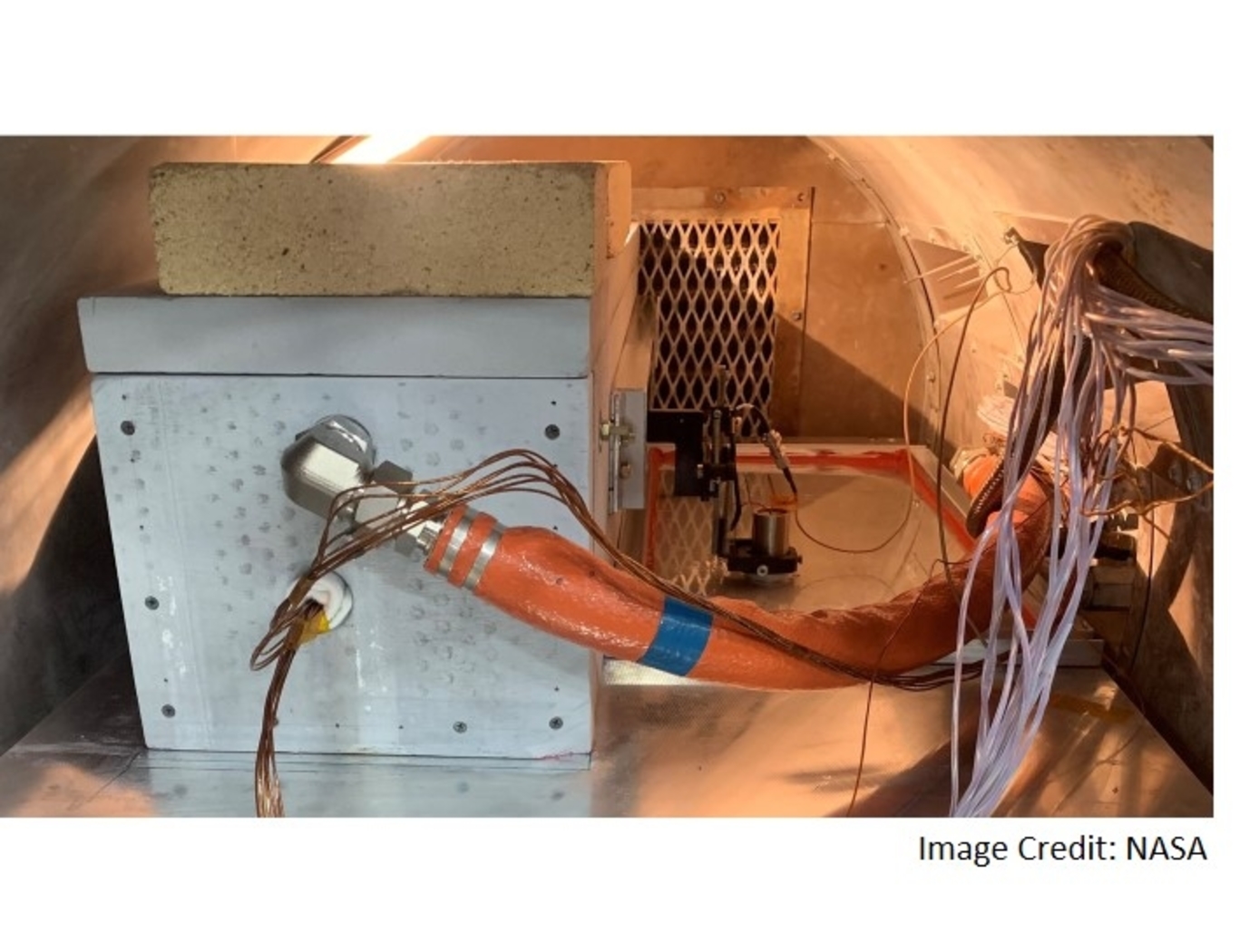
NASA's System for In-situ Defect (e.g., porosity, fiber waviness) Detection in Composites During Cure consists of an ultrasonic portable automated C-Scan system with an attached ultrasonic contact probe. This scanner is placed inside of an insulated vessel that protects the temperature-sensitive components of the scanner. A liquid nitrogen cooling systems keeps the interior of the vessel below 38°C. A motorized X-Y raster scanner is mounted inside an unsealed cooling container made of porous insulation boards with a cantilever scanning arm protruding out of the cooling container through a slot. The cooling container that houses the X-Y raster scanner is periodically cooled using a liquid nitrogen (LN2) delivery system. Flexible bellows in the slot opening of the box minimize heat transfer between the box and the external autoclave environment. The box and scanning arm are located on a precision cast tool plate. A thin layer of ultrasonic couplant is placed between the transducer and the tool plate. The composite parts are vacuum bagged on the other side of the tool plate and inspected. The scanning system inside of the vessel is connected to the controller outside of the autoclave. The system can provide A-scan, B-scan, and C-scan images of the composite panel at multiple times during the cure process.
The in-situ system provides higher resolution data to find, characterize, and track defects during cure better than other cure monitoring techniques. In addition, this system also shows the through-thickness location of any composite manufacturing defects during cure with real-time localization and tracking. This has been demonstrated for both intentionally introduced porosity (i.e., trapped during layup) as well processing induced porosity (e.g., resulting from uneven pressure distribution on a part). The technology can be used as a non-destructive evaluation system when making composite parts in in an oven or an autoclave, including thermosets, thermoplastics, composite laminates, high-temperature resins, and ceramics.
Materials and Coatings
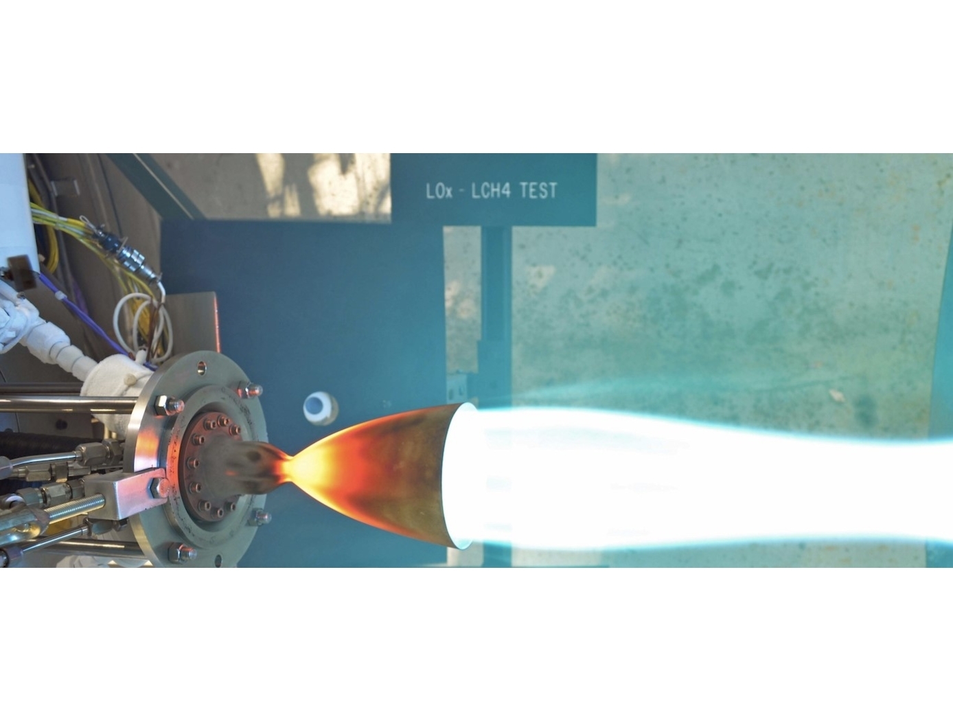
Oxide Dispersion Strengthened Medium Entropy Alloy
NASA's ODS-MEA maintains properties up to 1100°C and is not susceptible to deleterious phase changes when exposed to extreme temperatures, an issue ubiquitous to Ni- based superalloys such as Inconel-625 and Inconel-718. Yttria particles are dispersed throughout the alloy to maximize strength and creep resistance at high temperatures using a novel fabrication technique. This technique employs an acoustic mixer to stir nano-scale Yttria oxide powder within a metallic matrix powder, creating a film of Yttria surrounding the larger metallic powder particles. Solid components are then produced from this mixture via SLM, during which the laser disperses the Yttria particles throughout the microstructure. Ultimately, the process eliminates the many expensive and time-consuming steps in the production of ODS alloys via traditional mechanical alloying. NASA's process has been shown to fabricate components with 10x improvement in creep rupture life at 1100°C and provides a 30% increase in strength over what is currently possible with 3D printed parts. The new ODS-MEA composition may find applications where ODS alloys are currently used (e.g., those involving extreme thermal environments). Applications may also include areas where such properties are desirable but the resource-intensive nature and/or inability to produce highly complex geometries via conventional processes ultimately renders their use uneconomical or infeasible. Such uses include gas turbine components (for which increasing inlet temperature enables improved efficiency) for power generation, propulsion (rockets, jet engines, etc.), industrial processes, nuclear energy applications, and sample preparation equipment in the mining and cement production industries, among many others.

