Outer Aileron Yaw Damper
aerospace
Outer Aileron Yaw Damper (DRC-TOPS-1)
A lightweight alternative to rudders for aircraft with spanwise adaptive wings
Overview
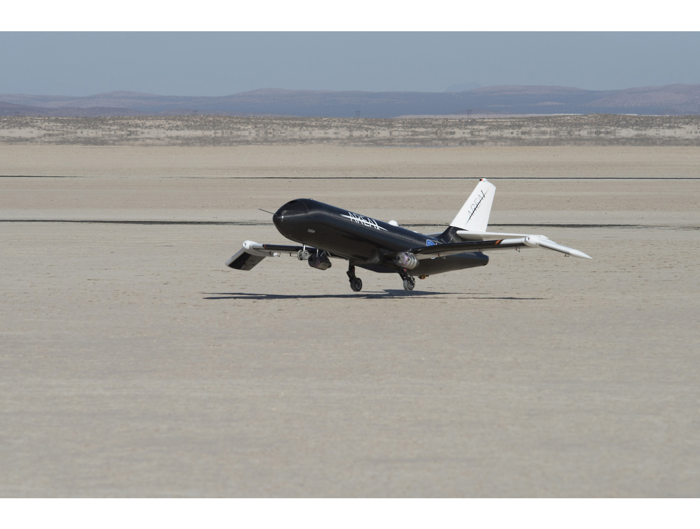
In recent years, NASA, along with partners Boeing and Area-I Inc., have developed the spanwise adaptive wing (SAW). SAWs leverage a thermally-triggered actuator made from a NASA-developed shape memory alloy (SMA) to allow outer portions of aircraft wings and control surfaces to be folded to achieve optimal angles during flight. For supersonic aircraft, SAWs can reduce drag and increase performance during the transition from subsonic to supersonic speeds. For subsonic aircraft, SAWs offer increased control and reduced dependency on the tail rudder and associated hydraulic systems - a particularly heavy part of the aircraft.
Engineers at NASA AFRC realized the aircraft weight savings that could be achieved by reducing or eliminating rudder dependency, since this would allow for rudder size to be reduced. So, they set out to develop an alternative system capable of providing the same "yaw control" functionality as traditional rudders. This work resulted in the invention of NASAs outer aileron yaw damper system, which includes novel control algorithms that drive flight control surfaces to produce desired flight conditions.
The Technology
Rudders have long served as the primary flight control surface as is pertains to aircraft yaw. Breaking this mold, NASA's SAW technology is a game-changing development in aircraft wing engineering that reduces rudder motion required to control aircraft. The benefits of reduced rudder dependency led NASA to develop the outer aileron yaw damper to further decrease or eliminate rudder dependency for aircraft using SAWs.
As mentioned, SAWs use shape memory alloy actuators to articulate the outer portion of the wing, effectively creating a movable wingtip. NASA's invention uses an outer aileron located on the wingtips, which is driven (along with the inner ailerons) by a novel control algorithm. The control algorithm, taking into account the wingtip positions, manipulates the outer ailerons to achieve the desired yaw rate. At the same time, it positions the inner ailerons to counter roll rate resulting from the outer aileron. In other words, the control algorithm calculates a control surface ratio (i.e., position of inboard aileron and outboard aileron) that produces desired yaw and roll accelerations.
The system can also be used to offset the existing rudder in current or future aircraft designs. A second part of NASAs novel outer aileron control algorithm modifies the aircrafts rudder loop gain in proportion to outer aileron usage. This allows the outer ailerons and rudder to work in tandem, while at the same time reducing rudder usage.
As a result of this NASA invention, required rudder usage can be reduced or eliminated for aircraft with SAWs. Consequently, the size of rudders and vertical tail structures can be reduced, which in turn reduces weight and parasitic drag. The result is an aircraft with increased performance and fuel efficiency.

Benefits
- Reduced aircraft weight: Less rudder dependency enables aircraft designs with smaller rudders and vertical tail structures, significantly decreasing vehicle weight.
- Decreased drag: Rudder and vertical tail structure size reductions may reduce parasitic drag.
- Fuel efficiency: Less weight and drag lead to reduced aircraft fuel consumption.
Applications
- Subsonic aircraft design
- Supersonic aircraft design
Technology Details
aerospace
DRC-TOPS-1
DRC-018-017
Patent Pending
|
Tags:
|
|
|
Related Links:
|
Similar Results

Shape Memory Alloy (SMA)-Enabled Actuators
Actuators typically have large footprints and mass to meet the power output needed for operation, leading to design hurdles for aircraft and space applications. Innovators at NASA Glenn developed two novel actuators with different configurations of tubes of SMA to provide rotary output. The SMA tubes are deformed in their martensitic condition and when exposed to a thermal stimulus, the tubes will revert to their original state while providing rotary motion.
One variation of the innovation nests the SMA tubes within a rotary actuator imparting several technical benefits. Nested SMA tubes can decrease the length of the actuator while achieving the same twist angle. For the same actuator length, a nested configuration of SMA tubes can multiply the twist angle and improve the power output. A second variation utilizes SMA components as transmission elements in a ring drive gear to enable continuous rotation in one direction. Previous similar SMA actuators rotate in one direction while heating and the other while cooling, which can limit the output of the rotary actuator. The innovation developed by NASA allows for continuous rotation in ANY direction, thereby allowing the rotational output capability to be independent from the amount of cyclic angular twist provided by the SMA tubes.

How to Train Shape Memory Alloys
Glenn researchers have optimized how shape memory alloys (SMAs) are trained by reconceptualizing the entire stabilization process. Whereas prior techniques stabilize SMAs during thermal cycling, under conditions of fixed stress (known as the isobaric response), what Glenn's innovators have done instead is to use mechanical cycling under conditions of fixed temperature (the isothermal response) to achieve stabilization rapidly and efficiently. This novel method uses the isobaric response to establish the stabilization point under conditions identical to those that will be used during service. Once the stabilization point is known, a set of isothermal mechanical cycling experiments is then performed using different levels of applied stress. Each of these mechanical cycling experiments is left to run until the strain response has stabilized. When the stress levels required to achieve stabilization under isothermal conditions are known, they can be used to train the material in a fraction of the time that would be required to train the material using only thermal cycling. As the strain state has been achieved isothermally, the material can be switched back under isobaric conditions, and will remain stabilized during service. In short, Glenn's method of training can be completed in a matter of minutes rather than in days or even weeks, and so SMAs become much more practical to use in a wide range of applications.

Real-Time Drag Opti-mization Control Framework
According to the International Air Transport Association statistics, the annual fuel cost for the global airline industry is estimated to be about $140 billion in 2017. Therefore, fuel cost is a major cost driver for the airline industry. Advanced future transport aircraft will likely employ adaptive wing technologies that enable the wings of those aircraft to adaptively reconfigure themselves in optimal shapes for improved aerodynamic efficiency throughout the flight envelope. The need for adaptive wing technologies is driven by the cost of fuel consumption in commercial aviation. NASA Ames has developed a novel way to address aerodynamic inefficiencies experienced during aircraft operation. The real-time drag optimization control method uses an on-board, real-time sensor data gathered from the aircraft conditions and performance during flight (such as engine thrust or wing deflection). The sensor data are inputted into an on-board model estimation and drag optimization system which estimates the aerodynamic model and calculates the optimal settings of the flight control surfaces. As the wings deflect during flight, this technology uses an iterative approach whereby the system continuously updates the optimal solution for the flight control surfaces and iteratively optimizes the wing shape to reduce drag continuously during flight. The new control system for the flight control surfaces can be integrated into an existing flight control system. This new technology can be used on passenger aircraft, cargo aircraft, or high performance supersonic jets to optimize drag, improve aerodynamic efficiency, and increase fuel efficiency during flight. In addition, it does not require a specific aircraft math model which means it does not require customization for different aircraft designs. The system promises both economic and environmental benefits to the aviation industry as less fuel is burned.

Improved Fixed-Wing Gust Load Alleviation Device
Gust loads may have detrimental impacts on flight including increased structural and aerodynamic loads, structural deformation, and decreased flight dynamic performance. This technology has been demonstrated to improve current gust load alleviation by use of a trailing-edge, free-floating surface control with a mass balance. Immediately upon impact, the inertial response of the mass balance shifts the center of gravity in front of the hinge line to develop an opposing aerodynamic force alleviating the load felt by the wing. This passive gust alleviation control covering 33% of the span of a cantilever wing was tested in NASA Langleys low speed wind tunnel and found to reduce wing response by 30%.
While ongoing experimental work with new laser sensing technologies is predicted to similarly reduce gust load, simplicity of design of the present invention may be advantageous for certification processes. Additionally, this passive technology may provide further gust alleviation upon extending the use of the control to the entire trailing edge of the wing or upon incorporation with current active gust alleviation systems.
Importantly, the technology can be easily incorporated into to the build of nearly all fixed wing aircrafts and pilot control can be maintained through a secondary trim tab. Though challenging to retrofit, passive gust alleviation could enable use of thinner, more efficient wings in new plane design.
.jpg)
Shape Memory Alloy Mechanisms for CubeSats
Most spacecraft feature release, retention, and deployment devices as key components, because these devices achieve on-demand configurability of solar panels, probes, antennas, scientific instruments, fairings, etc. Until now, designing and using such devices in small spacecraft has been a challenge, because their mass, volume, and power requirements are significant and can impose design constraints. CubeSats, in particular, often need to deploy several structures (such as solar arrays) simultaneously, which prior-art deployment devices have not been able to manage effectively. Glenn's innovation embeds SMAs within the components so the structures can be retained during launch, then released and deployed in orbit. The release and retention device is controlled by an SMA activated pin puller to disengage the release plate from the hooks holding the solar arrays. Once released, the SMA hinge is passively enabled to the deployed state. When ready on orbit, the mechanism is commanded to release and electrical power is sent to the SMA actuator, releasing the component to its deployed state. The component is deployed to its final position through the use of hinges, which are activated passively with SMA spring strips. The retention and release device and hinge are substantially smaller and lighter than deployment mechanisms have ever been and can deploy simultaneously with great reliability. Having already been successfully deployed on a NASA mission, Glenn's innovation is a game-changing technology for CubeSats and other small satellites.

