Variable Visibility Glasses for Instrument Flight Training
instrumentation
Variable Visibility Glasses
for Instrument Flight Training (LAR-TOPS-101)
Safer and more comfortable glasses for selectively limiting the view of pilot trainees
Overview
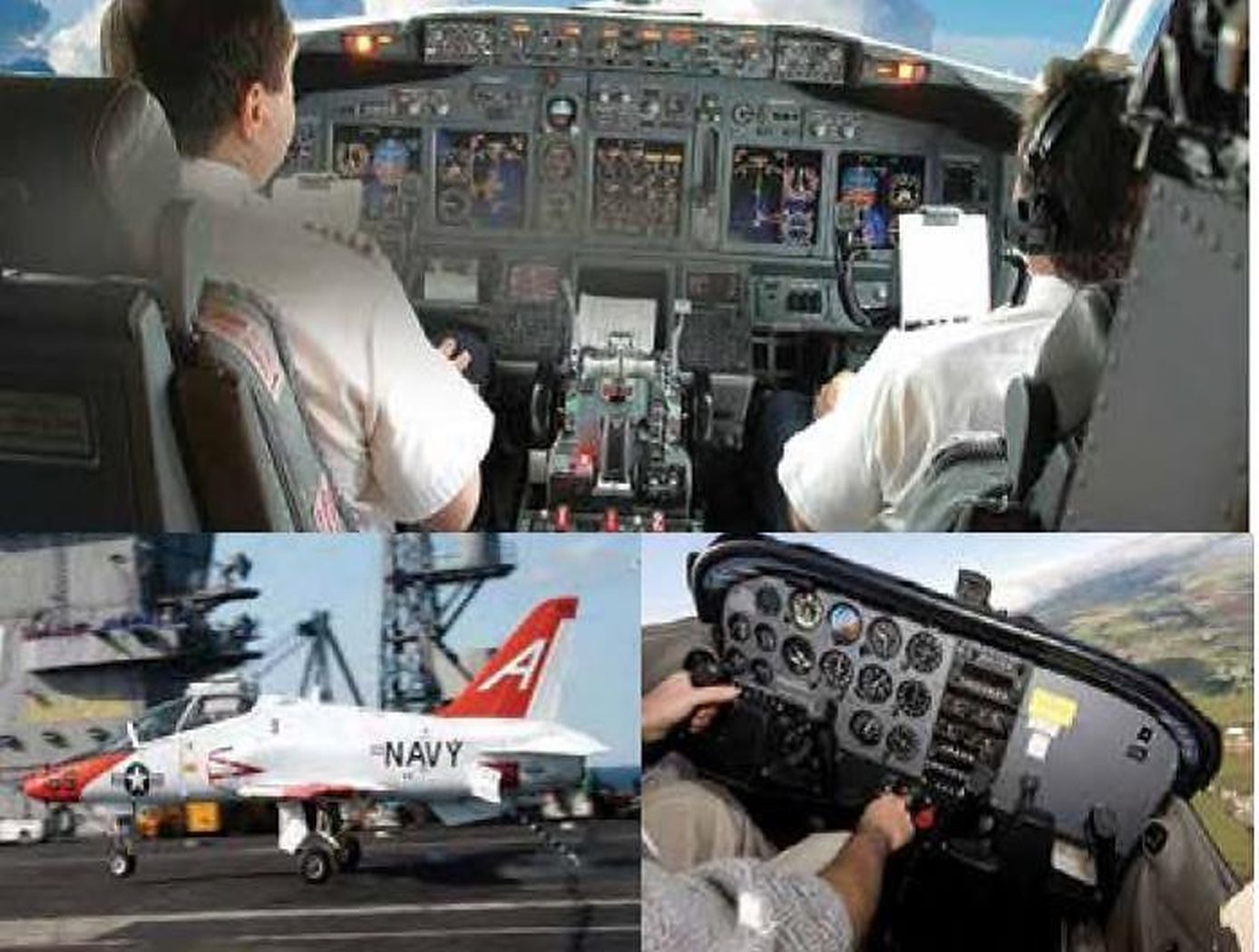
During instrument flight training the pilot must have his/her view through the aircraft windscreen restricted to simulate low / visibility conditions while permitting the pilot to view the instrument panel. In one current method, a hood is draped across the aircraft windscreen, or a face mask or blackened glasses is worn by the pilot. All such current methods create potentially hazardous disorientation and an unnatural environment for the trainee. In particular, the face mask and blackened glasses restrict the pilots peripheral vision and require uncomfortable and unnatural head positions in order to see the entire instrument panel.
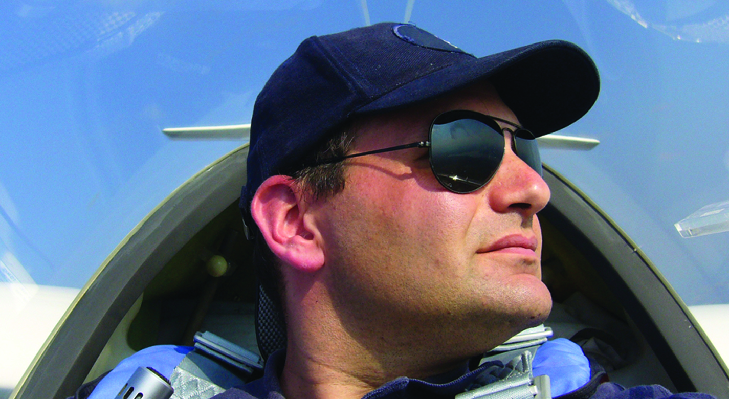
Researchers at NASA's Langley Research Center have developed and tested special glasses to be worn by a pilot during instrument flight training. Using novel sensors to determine head position, the glasses restrict the view out of the aircraft windscreen but allow the pilot to clearly see the entire instrument panel, providing a much more realistic low visibility instrument flying experience.
The Technology
The technology combines electroactively controlled liquid crystal lenses with a means for determining the pilots head position. When the pilots head is positioned to look outside the front or side windscreens, the lenses restrict light transmission. When the pilots head is lowered to view the instrument panel or other cockpit displays, the lenses allow light transmission so that the view of the instruments is unimpeded. Light transmission through the lenses can be selectively controlled by the system, ranging from 0.1% to 10%. The lenses are mounted in conventional eyeglass frames.
The frames include a detection system to determine the position and orientation of the pilots head. Circuits within the frames activate the lenses to restrict light transmission when the pilots head is oriented to look out the windscreen. A PC, linked to the aircraft flight computer or altimeter, is also in the control loop and turns off the system to allow unimpeded visibility when the aircraft is below 200 feet or for other specified conditions.
The technology readiness level of this invention is at stage seven with a prototype having been tested.


Benefits
- Safer - co-pilot visibility is not impeded, and the system is deactivated below a specified altitude
- Improved comfort system - uses conventional eyeglass frames, which are relatively lightweight and do not restrict the pilots movement
- Compatible with existing eyewear - system can be easily modified to fit over prescription eyeglasses or sunglasses
- More natural - natural head movements trigger the system to allow unimpeded visibility of the instruments and cockpit displays
- Improved flight experience - reduces potential for pilot disorientation so the trainee can focus on flying the aircraft
Applications
- Pilot glasses - for instrument flight training and simulation of reduced visibility conditions
- Military goggles - provide protection to aircrews from lasers or bright detonations
- Gaming and virtual reality goggles - restrict or allow selective vision based on users line of sight
- Transition lenses for eye wear - for lenses that darken when looking toward the Sun
Similar Results

Optical Head-Mounted Display System for Laser Safety Eyewear
The system combines laser goggles with an optical head-mounted display that displays a real-time video camera image of a laser beam. Users are able to visualize the laser beam while his/her eyes are protected. The system also allows for numerous additional features in the optical head mounted display such as digital zoom, overlays of additional information such as power meter data, Bluetooth wireless interface, digital overlays of beam location and others. The system is built on readily available components and can be used with existing laser eyewear. The software converts the color being observed to another color that transmits through the goggles. For example, if a red laser is being used and red-blocking glasses are worn, the software can convert red to blue, which is readily transmitted through the laser eyewear. Similarly, color video can be converted to black-and-white to transmit through the eyewear.

Reflection-Reducing Imaging System for Machine Vision Applications
NASAs imaging system is comprised of a small CMOS camera fitted with a C-mount lens affixed to a 3D-printed mount. Light from the high-intensity LED is passed through a lens that both diffuses and collimates the LED output, and this light is coupled onto the cameras optical axis using a 50:50 beam-splitting prism.
Use of the collimating/diffusing lens to condition the LED output provides for an illumination source that is of similar diameter to the cameras imaging lens. This is the feature that reduces or eliminates shadows that would otherwise be projected onto the subject plane as a result of refractive index variations in the imaged volume. By coupling the light from the LED unit onto the cameras optical axis, reflections from windows which are often present in wind tunnel facilities to allow for direct views of a test section can be minimized or eliminated when the camera is placed at a small angle of incidence relative to the windows surface. This effect is demonstrated in the image on the bottom left of the page.
Eight imaging systems were fabricated and used for capturing background oriented schlieren (BOS) measurements of flow from a heat gun in the 11-by-11-foot test section of the NASA Ames Unitary Plan Wind Tunnel (see test setup on right). Two additional camera systems (not pictured) captured photogrammetry measurements.
.jpg)
Airborne Background Oriented Schlieren Technique
This invention is an imaging method that requires very simple optics on an airborne vehicle, a camera with an appropriate lens, and an area on the ground that provides visual texture. The complexity with this method is in the image processing and not as much with the hardware or positioning, making Background Oriented Schlieren (BOS) an attractive candidate for obtaining high spatial resolution imaging of shock waves and vortices in flight. First, images are obtained of a visually textured background pattern from an appropriate altitude. Next, a series of images are collected of a vehicle in flight below the observer vehicle and over the same spot on the ground that serves as a background pattern. Shock waves are deduced from distortions of the background pattern resulting from the change in refractive index due to density gradients. The invention requires special software to create the schlieren images. The schlieren image is a contour plot of a two-dimensional data array of measured distortions, in pixel units. The results are used by researchers to help understand the flow phenomenon and compare to computational models. The BOS method also yields measured deflection distances, which can be used to determine the strength of a given density gradient. The system design and flight planning were based on the camera characteristics, airplane coordination, and airspace limitations.

Computational Visual Servo
The innovation improves upon the performance of passive automatic enhancement of digital images. Specifically, the image enhancement process is improved in terms of resulting contrast, lightness, and sharpness over the prior art of automatic processing methods. The innovation brings the technique of active measurement and control to bear upon the basic problem of enhancing the digital image by defining absolute measures of visual contrast, lightness, and sharpness. This is accomplished by automatically applying the type and degree of enhancement needed based on automated image analysis.
The foundation of the processing scheme is the flow of digital images through a feedback loop whose stages include visual measurement computation and servo-controlled enhancement effect. The cycle is repeated until the servo achieves acceptable scores for the visual measures or reaches a decision that it has enhanced as much as is possible or advantageous. The servo-control will bypass images that it determines need no enhancement.
The system determines experimentally how much absolute degrees of sharpening can be applied before encountering detrimental sharpening artifacts. The latter decisions are stop decisions that are controlled by further contrast or light enhancement, producing unacceptable levels of saturation, signal clipping, and sharpness.
The invention was developed to provide completely new capabilities for exceeding pilot visual performance by clarifying turbid, low-light level, and extremely hazy images automatically for pilot view on heads-up or heads-down display during critical flight maneuvers.

Reconfigurable Image Generator and Database Generation System
The system, the Reconfigurable Image Generator (RIG), consists of software and a hardware configuration, and a Synthetic Environment Database Generation System (RIG-DBGS). This innovative Image Generator (IG) uses Commercial-Off-The-Shelf (COTS) technologies and is capable of supporting virtually any display system. The DBGS software leverages high-fidelity real-world data, including aerial imagery, elevation datasets, and vector data. Through a combination of COTS tools and in-house created applications, the semi-automated system can process large amounts of data in days rather than weeks or months, a disadvantage of manual database generation. A major benefit of the RIG technology is that existing simulation users can leverage their investment in existing real-time 3D databases (such as OpenFlight) as part of the RIG system.


