Deployable Composite Boom
mechanical and fluid systems
Deployable Composite Boom (LAR-TOPS-328)
Low weight bistable collapsible tubular mast
Overview
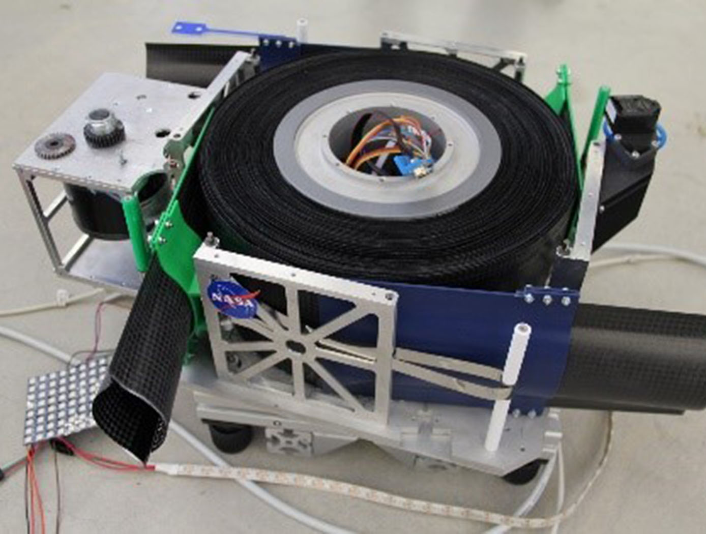
A sister to SHEARLESS booms, the Bistable Collapsible Tubular Mast (Bi-CTM) boom, offers compact storage on a cylindrical drum that deploys a composite material boom with a closed tubular cross section that has unmatched bending and torsional stiffness for the mass of the thin-shell structure. The Bi-CTM is also scalable for long booms given the load carrying capacity.
The Bi-CTM's two omega-shaped composite thin-shells form a bonded closed section which can spool onto a relatively compact drum for compact launch packaging and provide unparalleled stiffness to mass ratio when deployed. When using the booms as beam-column structures with a primarily compressive load component, this ratio determines the structural mass efficiency of the components, making the Bi-CTM exceptional for lightweight deployable structural rigging with higher load demands.
The improved dimensional and thermal stability offered by the closed-section shape and low coefficient of thermal expansion materials of the Bi-CTM, enables the use of the boom technology in precision applications that require high stability in harsh environments.
The Technology
Just like a kid's slap bracelet, the Bi-CTM design includes a secondary stable low-energy state aside from the rigid deployed state. The result is that the Bi-CTM is not under high-spring stress when coiled up which simplifies the stowage process as well as enabling a more controllable extension of the boom. The simplified stowage process enables reduced size, mass and complexity of the storage and deployment mechanism system.
Compared to the majority of deployable thin-shell booms, which have at best a semi-open cross section, this true closed-cross-section boom is stronger, while keeping the compact nature of rollable booms, and is able to overcome both bend and twist buckling related limitations.
Using omega-shaped cross sections with optionally circular, parabolic or ellipsoidal segments, where each half of these thin-shell composite booms can use equal (symmetric boom) or different (asymmetric boom) cross section geometry and/or composite laminates, offers a great deal of boom customization in terms of stable coiled diameter and structural properties.
Bi-CTM boom design optimization provides for maximized area moments of inertia and torsional constant, which related to the boom stiffness and the loading capacity, while remaining a bistable design.

Benefits
- Enables a lightweight expandable structure that can be stowed compactly
- Enhanced torsional stiffness
- Enhanced dimensional and thermal stability for precision applications
- Inexpensive to fabricate
- Highly customizable design
Applications
- Deployable space structures (solar panels, antennas, solar sails, drag augmentation devices, instrument booms, hinges, etc.)
- Deployable terrestrial structures (emergency shelters, clean rooms, self-erectable observation or communication towers, etc.)
- Backpack solar collectors
- Inspection booms (down-pipe cameras, hazardous environments, etc.)
Technology Details
mechanical and fluid systems
LAR-TOPS-328
LAR-19421-1
LAR-19421-1-CON
Inducing bistability in Collapsible Tubular Mast booms with thin-ply composite shells. Andrew J. Lee and Juan M. Fernandez. Composite Structures Volume 225, 1 October 2019, 111166. https://www.sciencedirect.com/science/article/pii/S0263822319307706?via%3Dihub
Bistability in Collapsible Tubular Mast Booms. Juan M. Fernandez and Andrew J. Lee. International Conference on Advanced Lightweight Structures and Reflector Antennas, September 19-21, 2018. https://ntrs.nasa.gov/citations/20190033365
Characterization and modeling of Large Collapsible Tubular Mast Booms. Olive R. Stohlman, Martin E. Zander and Juan M. Fernandez. AIAA Scitech 2021 Forum, January 2021. AIAA 2021-0903. https://arc.aiaa.org/doi/epdf/10.2514/6.2021-0903
Bistable Deployable Composite Booms With Parabolic Cross-Sections. Andrew J. Lee, Juan M. Fernandez and Jacob G. Daye. AIAA SCITECH 2022 Forum, January 2022. AIAA 2022-2264. https://arc.aiaa.org/doi/10.2514/6.2022-2264
Similar Results

SHEAth-based Rollable LEnticular-Shaped and Low-Stiction (SHEARLESS) Composite Booms
The SHEARLESS composite boom has a rollable structure with a large moment of inertia per unit of stored height that does not suffer from shear-derived problems. The boom is fabricated from joining two independent tape-springs front-to-front with the use of a durable seamless polymer sleeve. This sleeve allows the two parts to slide past each other during the coiling/deployment process so as to minimize shear and its derived problems. The innovation enables a lightweight structure that can be stowed on a reel without appreciable shear stresses developing in its constitutive composite parts, allowing for unprecedentedly small coiling diameters for the total thickness of the structure. As demonstrated, through specific laminate design of the two inner composite parts, the SHEARLESS composite boom can also be fabricated with a special inherent feature, bi-stability, which enables designs with minimal mechanisms and aids in deployment controllability and reliability.

Multi-Link Spherical Joint
The Multi-Link Spherical Joint developed at NASA Johnson Space Center provides a substantial improvement over typical joints in which only two linearly actuated links move independently from one another. It was determined that the rotation point of a trussed link needed to be collocated at a shared point in space for maximum articulation. If not allowed separate rotation, the line of action through a universal joint and hinge acts effectively as another linkage. This leads to a much more complex and uncontrollable structure, especially when considering multiple dimensions.
Comprising the Multi-Link Spherical Joint, a spherical shell encases the cupped ends of each six possible attachments and allows each of those attachments to be independently controlled and rotated without inhibiting the motion of the others. To do this, each link is precisely limited to 15 degrees of rotation off the link centerline, thus allowing a total of 30 degrees of rotation for each link. The shell-and-cup structure can handle the loads of linear actuators that may be used to control and vary the geometry of a truss system utilizing the new joint technology. The calculated operating load that the truss system must handle can be used to scale the size of the joint, further allowing customization of any potential truss system. Additionally, the incorporated linear actuators can be controlled and powered by wiring routed through the joint without putting undo stress on the wires during operation. Accordingly, this innovative joint technology enables more efficient deployment and precise operation of articulating structures.
The Multi-Link Spherical Joint is at technology readiness level (TRL) 4 (component and/or breadboard validation in laboratory environment) and is available for patent licensing. Please note that NASA does not manufacture products itself for commercial sale.

Composite Joint Connector
This technology is a joint connector for application between two or more tubular parts, or to connect one or more tubular parts to a fixed structure. This attachment technology is more structurally efficient and reduces failure characteristics due to the uniformity of composite material across the joint. In comparison to a typical joint, this technology reduces weight while minimizing stress variations that lead to structural failure. Moreover, typical joints must be bonded or screwed together, which further reduces efficiency. The invented technology, however, is designed so that it is both bonded and mechanically locked by design rather than relying on separate mechanical fasteners. The result is a design that mitigates failure of a structural joint.

In-Space Assembly of Structural Trusses and Shapes
The NASA innovation is based on a tessellation algorithm to break up a curved surface into identically sized equilateral surface polygons. Tessellation is a term used in mathematics that describes the process of deconstructing a surface into non-overlapping shapes with no gaps. Using this NASA innovation enables a curved-surface truss structure to be designed and built using all identical module and strut components. A key feature of this innovation is the use of a “multi-nut” connector, which enables curved surface truss structures to be assembled from identical truss modules. Uniform truss modules with customizable multi-nut connectors can be used to construct a curved-surface structure. The algorithm is a design approach for any size or surface shape.
The NASA innovation represents a major breakthrough due to:
• Versatility to a variety of planar and curved structure shapes (cylinder, sphere, etc.)
• Ability to change the shape simply by updating the “multi-nut” connectors
• Commonality of truss modules and components
• Ease of assembly
• Efficiency of construction and weight
• Robotic assembly and servicing.
In addition to a range of space related applications – mirrors, antennas, habitats, storage containers, etc. – the innovation is also directly applicable to general terrestrial assembly of systems with curvature, including for example sports stadiums, airports, aquariums, convention centers, or bridges.

Method for discrete assembly of Cuboctahedron Lattice Materials
The novel technology is a method for the design, manufacture, and assembly of modular lattice structure based mechanical metamaterials composed of cuboctahedron unit cells. The main parameters for determining the behavior of an architected lattice material are 1. Lattice geometry: base unit cell topology defines joint connectivity and informs general lattice behavior (e.g. bending or stretch dominated), which can then be used for performance prediction relative to constituent material and density. Cell size (edge length) and edge thickness (cross section) can be used to calculate relative density; 2. Base constituent material: solid properties (mechanical, thermal, electrical, etc.) are used to calculate effective properties of resulting lattice, as well as to inform manufacturing processes.
The invention relates particularly to a cuboctahedral lattice geometry, which can be decomposed into face connected cuboctahedrons. The material used is determined by the manufacturing process, such as injection molding. This offers a range of high-performance options such as glass fiber and carbon fiber reinforced polymer (GFRP, CFRP) composites. The size of the lattice can vary based on the application. Molded individual faces (bottom left figure) are then assembled into the cuboctahedron voxel building block (bottom right figure). This assembly can be achieved with a number of methods, including permanent methods such as welding or gluing, or reversible methods such as bolting or riveting.

