COROTUB Corrugated Rollable Tubular Boom
Mechanical and Fluid Systems
COROTUB Corrugated Rollable Tubular Boom (LAR-TOPS-341)
A Longer, Stronger Boom for Small Satellites
Overview
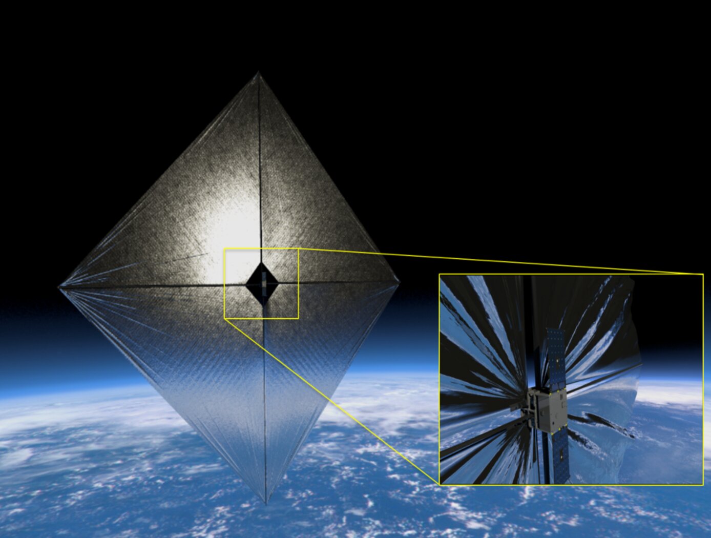
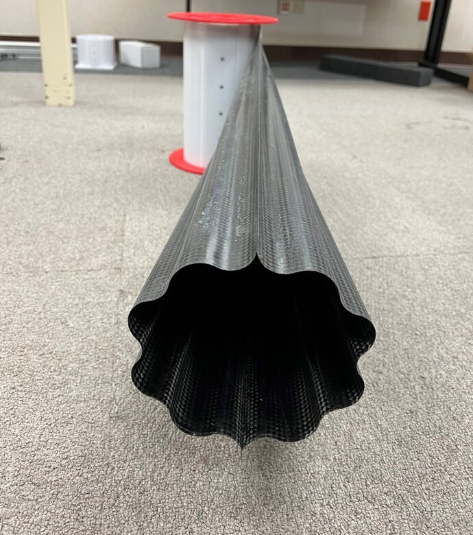
Deployable booms will enable the next generation of highly-functional satellites—hoisting the added solar panels and antennas that provide power, propulsion, and stronger communication capabilities to extend satellite life and enable travel further from earth. NASA’s new COROTUB boom is flattened, rolled, and stowed in a small package for easy transport to remote locations. When unfurled, it expands into a load-bearing structural boom. Compared to other thin-shelled booms, COROTUB has improved stiffness, strength, and stability, while maintaining the package size as other booms. COROTUB might be erected from an orbiting satellite to hoist and support equipment; or may be unfurled to set up emergency shelters, communication towers, or masts for antennas or solar power in remote areas on other planets, the moon, or here on earth. This NASA technology is available for your company to license and develop into a commercial product. NASA does not manufacture products for commercial sale.
The Technology
Deployable composite booms are particularly attractive in space constrained applications. Their high packaging volume efficiency enables relatively large spacecraft systems required for power generation, communications, or propulsion to be housed within small volumes. COROTUB is a monolithic closed-section tubular thin-shelled structure that’s been shown to scale efficiently up to 50m yet maintain its strength. COROTUB’s two corrugated thin shells form a closed section, which yields high bending and torsional stiffness, allowing for high dimensional stability. Computational analysis and early tests show that the corrugation provides increased strength against buckling, enabling longer booms and targeting more demanding structural applications than non-corrugated designs. The corrugation geometry that dictates the boom cross-section shape was informed by parametric studies to optimize the parameters that most influence the cross-section’s area moment of inertia and torsional constant. The corrugated designs were found to improve the boom bending and axial strength and to shorten the length of the boom transition from flat/rolled to deployed.


Benefits
- Lightweight: foldable and rollable structural material enables large antennas, radiators, solar panels and other instruments on satellites.
- Shorter transition length from the rolled up position to reach full deployment compared to non- corrugated booms, enabling more compact systems
- Higher bending strength and torsional stiffness compared to non-corrugated designs
- Reduced shape distortion during prolonged stowage while rolled
- Larger cross sections and longer lengths for boom designs to meet demanding structural applications (e.g., deployment against gravity, long lengths, etc.)
Applications
- Space: hoisting solar arrays, antennas, radiators, solar sails, drag cells, sun shields, etc.
- Planetary: for building large structures and or masts to support hardware for communications and power
- Terrestrial: can be hauled and unfurled into pole structures to build housing or masts to support hardware for communications and power in outpost areas
Technology Details
Mechanical and Fluid Systems
LAR-TOPS-341
LAR-19873-1
Fernandez, Juan and Volle, Christopher, Corrugated Rollable Tubular Booms (presentation). AIAA Scitech Forum (virtual). January 4-8, 2021.
|
Tags:
|
|
|
Related Links:
|
Similar Results

Deployable Composite Boom
Just like a kid's slap bracelet, the Bi-CTM design includes a secondary stable low-energy state aside from the rigid deployed state. The result is that the Bi-CTM is not under high-spring stress when coiled up which simplifies the stowage process as well as enabling a more controllable extension of the boom. The simplified stowage process enables reduced size, mass and complexity of the storage and deployment mechanism system.
Compared to the majority of deployable thin-shell booms, which have at best a semi-open cross section, this true closed-cross-section boom is stronger, while keeping the compact nature of rollable booms, and is able to overcome both bend and twist buckling related limitations.
Using omega-shaped cross sections with optionally circular, parabolic or ellipsoidal segments, where each half of these thin-shell composite booms can use equal (symmetric boom) or different (asymmetric boom) cross section geometry and/or composite laminates, offers a great deal of boom customization in terms of stable coiled diameter and structural properties.
Bi-CTM boom design optimization provides for maximized area moments of inertia and torsional constant, which related to the boom stiffness and the loading capacity, while remaining a bistable design.

Novel Antenna Concept for CubeSat Platforms
The side walls and railing rods of a CubeSat are replaced by RF radiators that double as supporting structures. The RF radiators are hollow railing rods with inner dimensions that function as a waveguide to carry RF energy at a desired frequency. Radiating slots are cut on two of the four sides of hollow tubes tube that are open to outside environment. Different operating frequency antennas may be placed at each of the Cubesats four corners. Thus the railing rods provide RF antenna functionality in addition to structurally supporting the CubeSat structure.
While this technology was designed for Cubesats, it may be utilized in any technology that utilizes a structural frame. The advantages of this system are increased reliability due to the elimination of deployment mechanisms and decreased payloads. Higher frequency
antennas with increased gain and directivity may be embedded into the rails. These higher frequencies are especially useful for remote sensing.

SHEAth-based Rollable LEnticular-Shaped and Low-Stiction (SHEARLESS) Composite Booms
The SHEARLESS composite boom has a rollable structure with a large moment of inertia per unit of stored height that does not suffer from shear-derived problems. The boom is fabricated from joining two independent tape-springs front-to-front with the use of a durable seamless polymer sleeve. This sleeve allows the two parts to slide past each other during the coiling/deployment process so as to minimize shear and its derived problems. The innovation enables a lightweight structure that can be stowed on a reel without appreciable shear stresses developing in its constitutive composite parts, allowing for unprecedentedly small coiling diameters for the total thickness of the structure. As demonstrated, through specific laminate design of the two inner composite parts, the SHEARLESS composite boom can also be fabricated with a special inherent feature, bi-stability, which enables designs with minimal mechanisms and aids in deployment controllability and reliability.

Multi-Link Spherical Joint
The Multi-Link Spherical Joint developed at NASA Johnson Space Center provides a substantial improvement over typical joints in which only two linearly actuated links move independently from one another. It was determined that the rotation point of a trussed link needed to be collocated at a shared point in space for maximum articulation. If not allowed separate rotation, the line of action through a universal joint and hinge acts effectively as another linkage. This leads to a much more complex and uncontrollable structure, especially when considering multiple dimensions.
Comprising the Multi-Link Spherical Joint, a spherical shell encases the cupped ends of each six possible attachments and allows each of those attachments to be independently controlled and rotated without inhibiting the motion of the others. To do this, each link is precisely limited to 15 degrees of rotation off the link centerline, thus allowing a total of 30 degrees of rotation for each link. The shell-and-cup structure can handle the loads of linear actuators that may be used to control and vary the geometry of a truss system utilizing the new joint technology. The calculated operating load that the truss system must handle can be used to scale the size of the joint, further allowing customization of any potential truss system. Additionally, the incorporated linear actuators can be controlled and powered by wiring routed through the joint without putting undo stress on the wires during operation. Accordingly, this innovative joint technology enables more efficient deployment and precise operation of articulating structures.
The Multi-Link Spherical Joint is at technology readiness level (TRL) 4 (component and/or breadboard validation in laboratory environment) and is available for patent licensing. Please note that NASA does not manufacture products itself for commercial sale.

Origami-based Deployable Fiber Reinforced Composites
Deployable space structures often rely upon telescoping or folding structures that either must be manually deployed or deployed by attached motors. These structures are often made from heavier (relative to carbon fiber composites) metals to provide enough strength to support a load. As such, there is a need for in-space structures that are lightweight, can be packaged compactly, and can be deployed easily.
The composite material developed here does not require high temperature baking to cure the polymer, rather relying on UV light to solidify the polymer component. The composite is then included into origami-based structures that can fold and deploy using the polymer shape memory effect. The composite is first trained to assume the deployed structural shape when heated; it is then folded like origami and frozen into the packaged shape for storage and launch. Combining the composite material with the origami-inspired design leads to high strength structures (can hold at least 600 kg on Earth). To date, a ~5-inch prototype structural bar has been produced using the UV-curable composite and further development is on-going at NASA Langley.
The deployable origami composite structures are at technology readiness level (TRL) 4 (component and/or breadboard validation in laboratory environment) and are available for patent licensing.


