Vertically Aligned Carbon Nanotubes
Materials and Coatings
Vertically Aligned Carbon Nanotubes (LEW-TOPS-27)
Formation of a composite with improved through thickness conductivity, interlaminar strength, fracture toughness and impact resistance
Overview
Innovators at NASA’s Glenn Research Center have developed a polymer matrix composite composed of layers that alternate between a thin carbon fiber veil layer coated with nanotubes and a thicker base carbon fiber reinforcement layer. The alternating fiber layers are held together by a curable epoxy resin. The resulting composite material provides improved interlaminar strength, fracture toughness and impact resistance. The carbon fiber veils can be evenly distributed throughout the composite or targeted to specific areas of a part that are likely to require reinforcement. For example, veils can be selectively situated at a leading edge of a wind turbine blade, a helicopter blade, an engine component, an air foil, or an aircraft nose section. Since the veils themselves do not impart strength or stiffness to the composite structure, any damage to the veils does not affect the integrity of the composite structure. The embedded carbon nanotubes can provide through thickness thermal and electrical conductivity. The electrically conductive nature of the nanocomposite veils allows for their application for added lightning strike protection and electromagnetic protection.
The Technology
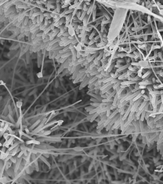
Formation of the inventive polymer composite matrix begins by growing carbon nanotubes directly on a veil substrate. The carbon nanotubes are grown from both sides of a non woven carbon fiber mat. The carbon nanotubes can be single or multi walled and can be grown to predetermined lengths. The veiled substrate is positioned between carbon fiber/ polymer prepreg layers such that the carbon nanotubes protrude into the reinforcement layers. The polymer composite matrix formed following curing of the resin exhibits improved interlaminar strength, fracture toughness and impact resistance. Because of the thinness of the veil layer, electricity can pass from conductive carbon nanotubes on one side of the veil to conductive carbon nanotubes on the other side of the veil. Electricity can also pass between two veils intercalated into the same reinforcement layer when the length of the nanotubes is sufficiently long enough to provide overlap within the reinforcement layers.

Benefits
- Allows formation of polymer matrix composite with improved damage tolerance, improved interlaminar strength and improved fracture toughness
- Flexible fabrication process allows veils to be distributed throughout the composite or selectively used in certain areas of a part that are likely to be subject to impacts
- Easy ability to modify the veil substrate materials and nanotube materials that can be used to fabricate the improved polymer matrix composite
- The carbon veil substrate and/or the conductive carbon nanotubes can be coated with metal particles to further increase the thermal and electrical capacity of the composite
Applications
- Nanomaterials (carbon nanotubes, graphene, nanofibers, nanoparticles, nanowires)
- Aerospace
- Automotive
- Power (ultracapacitors, windmill blades, thermal cells, batteries, fuel cells, solar cells, LEDs)
- Composites
|
Tags:
|
Similar Results

Carbon Fiber-Carbon Nanotube Yarn Hybrid Reinforcement
NASA's new material is a toughened triaxial braid made from ductile carbon nanotube (CNT) yarn hybridized with carbon fiber, which is ultimately used as reinforcement material to make toughened polymer matrix composites. The CNT yarn component of the reinforcement is solely responsible for adding toughness, while the processes used to optimize the fiber braiding parameters and tensile properties of the carbon fiber-CNT yarn hybrid tow material determine the overall improvement in tensile strength for resin impregnated fiber tows. Bundles of continuous carbon nanotube yarns are combined with a similar format of carbon fiber, yielding an easily scalable process.
Advantages of the material include reduced cost by eliminating use of toughening agents, increased ability to conform to highly complex geometries, greater environmental stability compared to aramid fiber reinforcements such as Kevlar, and possibly decreased density. Many hybrid reinforcements exhibit interfacial compatibility issues, which could lead to premature failure via crack propagation at the polymer matrix interface. In contrast, chemical similarities between the CNT yarn and carbon fiber constituents impart NASA's hybrid reinforcement material with excellent interfacial compatibility.
Potential applications include aerospace components, composite pressure vessels, wind turbine blades, automotive components, prosthetics, sporting equipment, construction reinforcement material, and other use-cases where strength-to-weight ratio is of utmost importance.

Continuous Fiber Composite for Use in Gears
Designers are constantly seeking to improve the power-to-weight ratio of components in rotorcraft and other flight vehicles. One approach has involved using lightweight carbon fiber composite materials to replace gear web portions and other components that are typically made from steel. The problem with using fiber composite materials comes when more complex shapes are required. To create thickness variation and other accommodations for complex shapes, manufacturers can stack cut continuous fiber plies and/or form short, fiber-reinforced composite material to the desired shape. Unfortunately, these methods leave cut fiber ends within the structure, which often become initial sites for high cycle fatigue damage in high speed, high power density applications. Glenn's new method tackles this problem with one of three approaches. The first approach is applicable to gears that are planar in shape and have a single hub and a single rim. The hub and web sections of the gear are made as an integrated structure with decreased thickness from the hub inner diameter to the web outer diameter. The thickness variation is accomplished using multiple layers of continuous fiber composite material formed to specific shapes and separated by filler materials. The second approach is applicable to gears that have an extended gear body in the axial direction rather than a simple planar structure. In this approach, the gear body is made using multiple layers of continuous fiber composite material in the shape of a solid of revolution. The third approach is a power transfer assembly made by combining approaches one and two. With any of these three approaches, the material can be tailored to the structure by the properties of fibers used, the number of fiber layers used, and the location of the fibers relative to the neutral axis of the structure. Glenn's innovation opens the door for carbon fiber composite materials to be used for many applications for which they were previously unsuited.

Conductive Polymer/Carbon Nanotube Structural Materials and Methods for Making Same
Carbon nanotubes (CNTs) show promise for multifunctional materials for a range of applications due to their outstanding combination of mechanical, electrical and thermal properties. However, these promising mechanical properties have not translated well to CNT nanocomposites fabricated by conventional methods due to the weak load transfer between tubes or tube bundles.
In this invention, the carbon nanotube forms such as sheets and yarns were modified by in-situ polymerization with polyaniline, a -conjugated conductive polymer. The resulting CNT nanocomposites were subsequently post-processed to improve mechanical properties by hot pressing and carbonization. A significant improvement of mechanical properties of the polyaniline/carbon nanotube nanocomposites was achieved through a combination of stretching, polymerization, hot pressing, and carbonization.

Healable Carbon Fiber Reinforced Composites
A composite fabrication process cycle was developed from composite precursor materials developed at LaRC to fabricate composite laminates. The precursor material is a pre-impregnated unidirectional carbon fiber preform, or prepreg. In the pre-pregging process, the high strength, structural reinforcing carbon fiber is wetted by a solution containing a self-healing polymer. The resulting material is of aerospace quality and exhibits a significant decrease of internal damage following impacts tests (using ASTM D 7137 standard).

Origami-based Deployable Fiber Reinforced Composites
Deployable space structures often rely upon telescoping or folding structures that either must be manually deployed or deployed by attached motors. These structures are often made from heavier (relative to carbon fiber composites) metals to provide enough strength to support a load. As such, there is a need for in-space structures that are lightweight, can be packaged compactly, and can be deployed easily.
The composite material developed here does not require high temperature baking to cure the polymer, rather relying on UV light to solidify the polymer component. The composite is then included into origami-based structures that can fold and deploy using the polymer shape memory effect. The composite is first trained to assume the deployed structural shape when heated; it is then folded like origami and frozen into the packaged shape for storage and launch. Combining the composite material with the origami-inspired design leads to high strength structures (can hold at least 600 kg on Earth). To date, a ~5-inch prototype structural bar has been produced using the UV-curable composite and further development is on-going at NASA Langley.
The deployable origami composite structures are at technology readiness level (TRL) 4 (component and/or breadboard validation in laboratory environment) and are available for patent licensing.

