High-Speed, Low-Cost Telemetry Access from Space
communications
High-Speed, Low-Cost Telemetry Access from Space (MFS-TOPS-62)
Programmable, lightweight, and adaptable software-defined radio
Overview
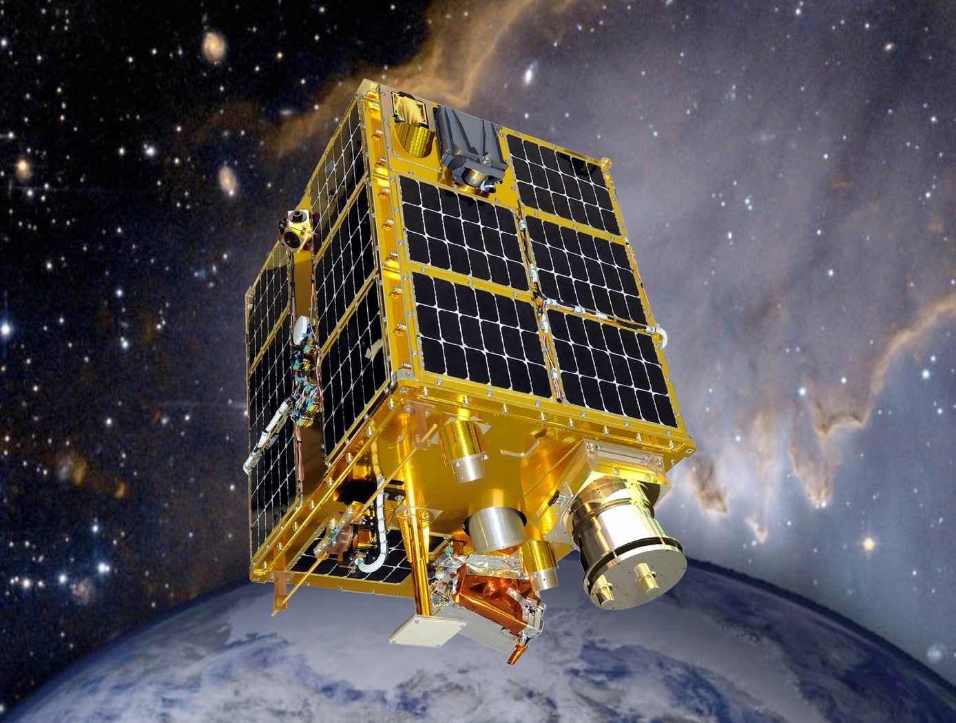
Researchers at NASA's Marshall Space Flight Center have developed software-defined radio (SDR) telemetry transceiver technology to collect and transmit data to and from small satellites and microsatellites. The SDR concept uses a minimal number of traditional analog radio frequency components to convert RF signals to a digital format. Digital signal processing replaces bulky radio frequency components and enables reduced cost as well as size, weight, and power requirements (SWaP). The NASA technology enables software and firmware updates that increase lifespan and efficacy of satellites, supporting a wide variety of changing radio protocols as they are developed. A modular design enables inclusion of multiple band frequency transmitters and receivers (S band, X band, Ka band, etc.). The NASA SDR can find use in satellite applications in which cost savings, upgradability, and reliability are essential. A first-generation SDR has been flight tested on NASA's FASTSAT mission.
The Technology
NASA's SDR uses Field-Programmable Gate Array (FPGA) technology to enable flexible performance on orbit. A first-generation FM-modulated transceiver is capable of operating at up to 1 Mbps downlink and 50 kbps uplink, full duplex. An FPGA performs Reed-Solomon (255,223) encoding, decoding, and bit synchronization, providing Consultative Committee for Space Data Systems (CCSDS) and Near Earth Network (NEN) telemetry protocol compatibility. The transceiver accepts data from the onboard flight computer via a source synchronous RS422 interface.
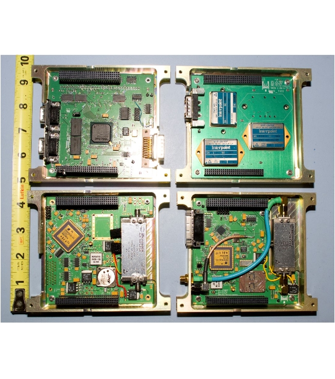
NASA's second-generation full duplex SDR, known as PULSAR (programmable ultra-lightweight system-adaptable radio, Figures 1 and 2 below) incorporates command receiver and telemetry transmitters, as well as updated processing and power capabilities. An S-band command receiver offers a max uplink data rate of 300 Kbps and built-in QPSK demodulation. X- and S-Band telemetry transmitters offer a max downlink data rate of 150 Mbps and flexible forward-error correction (FEC) using Reed-Solomon encoding (LDPC rate 7/8 and 1/2 convolution in development), and it uses QPSK modulation. The use of FEC adds an order of magnitude increase in telemetry throughput due to an improved coding gain. An onboard FPGA uses high-speed logic for uplink/downlink and encoding/decoding processes. Balloon flight testing has been conducted and is ongoing for PULSAR.


Benefits
- Adaptability: SDR enables support for changing radio protocols, implementation of new transponder types, and bug fixes while in service.
- Low cost: SDR enables production costs from $10,000-100,000s by leveraging high-quality componentry without the expense of qualification testing.
- High-speed data transmission: PULSAR's FEC coding enables 300kbps uplink and 150Mbps downlink rates.
- Reduced SWaP: Fewer required components by FPGA results in reduced payload weight and power consumption.
- Modular design: Hardware design enables flexible inclusion of different combinations of band frequency transmitters and receivers.
Applications
- Atmospheric studies: climate and terrestrial weather monitoring and forecasting
- Earth observation: transmission of imagery for urban planning, disaster monitoring, agriculture, etc.
- Ionospheric studies: observation of space weather phenomena
Technology Details
Sims, et al. Programmable Ultra-Lightweight System Adaptable Radio (PULSAR) Low-Cost Telemetry Access from Space. 27th Annual AIAA/USU Conference on Small Satellites.
Varnavas, et al.The Use of Field-Programmable Gate Arrays (FPGA) in Small Satellite Communication Systems. International Conference on Advances in Satellite and Space Communications (SPACOMM) 2015.
Varnavas, et al.The Use of Field-Programmable Gate Arrays (FPGA) in Small Satellite Communication Systems. International Conference on Advances in Satellite and Space Communications (SPACOMM) 2015.
|
Tags:
|
Similar Results

Tunable Multi-Tone, Multi-Band, High-Frequency Synthesizer
Glenn's revolutionary new multi-tone, high-frequency synthesizer can enable a major upgrade in the design of high data rate, wide-band satellite communications links, in addition to the study of atmospheric effects. Conventional single-frequency beacon transmitters have a major limitation: they must assume that atmospheric attenuation and group delay effects are constant at all frequencies across the band of interest. Glenn's synthesizer overcomes this limitation by enabling measurements to be made at multiple frequencies across the entire multi-GHz wide frequency, providing much more accurate and actionable readings.
This novel synthesizer consists of a solid-state frequency comb or harmonic generator that uses step-recovery semiconductor diodes to generate a broad range of evenly spaced harmonic frequencies, which are coherent and tunable over a wide frequency range. These harmonics are then filtered by a tunable bandpass filter and amplified to the necessary power level by a tunable millimeter-wave power amplifier. Next, the amplified signals are transmitted as beacon signals from a satellite to a ground receiving station. By measuring the relative signal strength and phase at ground sites the atmospheric induced effects can be determined, enabling scientists to gather essential climate data on hurricanes and climate change. In addition, the synthesizer can serve as a wideband source in place of a satellite transponder, making it easier to downlink high volumes of collected data to the scientific community. Glenn's synthesizer enables a beacon transmitter that, from the economical CubeSat platform, offers simultaneous, fast, and more accurate wideband transmission from space through the Earth's atmosphere than has ever been possible before.

Multi-and Wide-Band Single-Feed Patch Antenna
NASA's patch antenna technology exhibits higher operational bandwidth (on the order of 20%) than typical patch antennas (less than 10%) and can operate across integer-multiple frequency bands (e.g. S/X, C/X, S/C). Testing of the antenna design has demonstrated > 6dB of gain on both S and X bands (boresight), with an axial ratio of < 6dB and voltage standing wave ratio (VSWR) < 3:1 throughout the entire near-Earth network (NEN) operating bands (22.4GHz and 88.4GHz) with hemispherical coverage. The patch size is on the order of 10 x 10 cm and with associated electronics, is about 1 cm in height.

Dynamic Range Enhancement of High-Speed Data Acquisition Systems
Electronic waveforms exist that exceed the capabilities of state-of-the-art data acquisition hardware that is commonly available. The electronic waveforms that need to be measured simultaneously contain wide bandwidth, high frequency content, a DC reference, high dynamic range, and a high crest factor. The NASA Glenn high-speed data acquisition system creates a voltage compression effect with a custom transfer function that is adapted to the voltage range, frequency bandwidth, and electrical impedance of both the test article and data acquisition device. The compression transfer function is later reversed (or decompressed) with a software algorithm to restore the original signal's voltage from the acquired data. The data is thus improved via better signal-to-noise ratio, better low-amplitude accuracy, better resolution, and preservation of high-frequency spectral content. The circuit can be realized with either passive components or both active and passive components. Either realization is specialized for the test article and data acquisition hardware.
This is an early-stage technology requiring additional development. Glenn welcomes co-development opportunities.

Space Link Extension Return Channel Frames (SLE-RCF) Software Library
The Space Link Extension Return Channel Frames (SLE-RCF) software library helps to monitor the health and safety of spacecraft by enabling space agency ground support and mission control centers to develop standardized and interoperable mission control applications for space telemetry data. The software library eliminates the need for missions to implement custom data communication designs to communicate with any ground station. The two main tasks accomplished via the SLE-RCF software library are processing user requests and receiving data from ground stations and ground support assets.
The software library contains three layers:
-SLE (Space Link Extension) for the abstract workings of the protocol
-DEL (Decoding and Encoding Layer) to decode and encode the abstract messages used by the SLE layer
-TML (Transport Mapping Layer) to transfer the encoded messages via some underlying transport layer protocol, such as as the transmission control protocol (TCP)
The library accepts configuration or SLE-RCF directives from the user and responds accordingly. Incoming data, both telemetry frames and status messages, are processed and the appropriate callback routines are triggered by the library.

Gateway Integrates Wireless Sensors with Existing Aircraft Systems at "the Speed of Software"
In traditional hardwired avionics systems, sensor integration requires installation of literally tons of physical cable that significantly increases vehicle weight and the time it takes to develop, maintain, and modify systems. Cabling also consumes space available for profitable payloads. Armstrong's technology uses software to incorporate new wireless capability without physically modifying existing avionics.
How It Works
Armstrong's gateway uses a software defined radio (SDR) to control the flow of information between various wireless devices and a vehicle's avionics. An SDR can be reprogrammed to communicate with a variety wireless communication protocols and frequencies via straightforward software modules—as opposed to wireless sensor-specific hardware—effectively eliminating the need to modify a vehicle's existing avionics hardware architecture.
The gateway employs publish-subscribe network architecture. Before takeoff, flight computers reques—tor subscribe to—specific pieces of information from the SDR gateway. Wireless sensor devices then provide their respective sensor measurements to the SDR gateway, where they are distributed—or published—to any flight computer that has subscribed to a specific measurement.
Why It Is Better
Armstrong's technology simplifies the process of designing wireless avionics networks by providing a single point of communication between wireless and wired systems. It functions as a layer of abstraction between wireless sensors and the system with which they interface. This approach also ensures that no wireless device can directly communicate with a flight computer unless subscribed prior to takeoff, thus protecting the system from malicious or errant transmissions.
Although specifically designed for aerospace systems, the gateway is both platform- and implementation-agnostic, with the potential to foster convergence between wireless technologies and existing systems in other industries. A manufacturer can add industrial Internet-of-Things capability without having to integrate new wireless interfaces into its preexisting network.
The gateway serves as a universal interface with virtually any wireless device for such applications as connected logistics, predictive maintenance, asset tracking, and much more.


