Sublimable Propellant Source for Iodine-fed Ion Propulsion System
propulsion
Sublimable Propellant Source for Iodine-fed Ion Propulsion System (MFS-TOPS-85)
Enables reliable and robust storage and delivery of iodine propellant to a thruster
Overview
NASAs Marshall Research Center has developed a system for generating iodine vapor from solid iodine, for use as a propellant in a Hall or ion thruster propulsion system.
Xenon has generally been the preferred propellant of choice for these spacecraft ion propulsion systems, but more recently iodine-based systems have gained significant attention due to comparable performance to xenon, and the system-level advantages of low storage pressure and higher storage density with more propellant per unit volume. However the solid iodine, in comparison to gaseous xenon, must be sublimated into a vapor for ionization, and a heat source must be used to increase the sublimation rate of the solid iodine to a level that is useful for propulsive purposes. The subject innovation is a spring-loaded mechanism to optimize the contact of the solid iodine with the heated structure in the zero-gravity environment of space.
The Technology
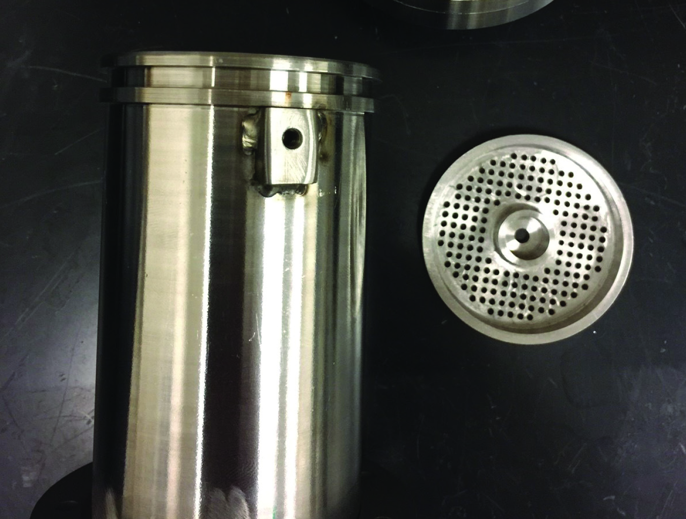
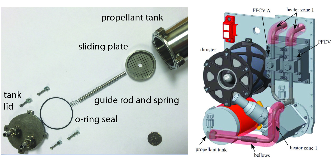
NASAs iodine vapor feed system is based on a mechanism that holds and maintains the solid iodine is contact with a heated surface, in this case the walls of the propellant tank. The mechanism provides a robust and reliable steady-state delivery of sublimated iodine vapor to the ion propulsion system by ensuring good thermal contact between the solid iodine and the tank walls.
To date, the technology development effort includes extensive thermal, mechanical and flow modelling together with testing of components and subsystems required to feed iodine propellant to a 200-W Hall thruster. The feed system has been designed to use materials that are resistant to the highly-reactive nature of iodine propellant. Dynamic modeling indicates that the feed system tubing can be built is such a way as to reduce vibrationally-induced stresses that occur during launch. Thermal modeling has been performed to demonstrate that the feed system heater power levels are sufficient to heat the tank and propellant lines to operating temperatures, and sublime the iodine in the storage tank to supply propellant for reliable and long-term operation.


Benefits
- Iodine propellant for ion thrusters offers significant improvements in volume/space efficiency over xenon propellant systems presently in use today.
- The propellant can be stored in its solid state at very low pressure, whereas xenon must be stored in a compressed gas state at high pressure requiring additional tankage structure to contain the gas.
- The technology has been the subject of considerable research effort and investment, and is nearing readiness for flight testing.
Applications
- Applications include the development of, and use of, iodine-based ion thruster propulsion systems. These advanced propulsion systems can be used in government sponsored deep-space missions, as well as in commercial and government orbital satellite applications where size and safety are of paramount interest.
Technology Details
propulsion
MFS-TOPS-85
MFS-33363-1
KA Polzin, JF Seixal, SL Mauro, AO Burt, A Martinez, AK Martin, The iodine Satellite (iSat) Propellant Feed System - Design and Development, in 35th International Electric Propulsion Conference, Atlanta, GA, Oct. 8-12, 2017. IEPC Paper 2017-11
Kurt A. Polzin, Steven R. Peeples, Armando Martinez, Joao F. Seixal, Stephanie Mauro, Adam O. Burt, and James L. Myers. "Engineering Model Propellant Feed System Development for an Iodine Hall Thruster Demonstration Mission", 52nd AIAA/SAE/ASEE Joint Propulsion Conference, AIAA Propulsion and Energy Forum, (AIAA 2016-4730)
Kurt A. Polzin, Steven R. Peeples, Armando Martinez, Joao F. Seixal, Stephanie Mauro, Adam O. Burt, and James L. Myers. "Engineering Model Propellant Feed System Development for an Iodine Hall Thruster Demonstration Mission", 52nd AIAA/SAE/ASEE Joint Propulsion Conference, AIAA Propulsion and Energy Forum, (AIAA 2016-4730)
|
Tags:
|
|
|
Related Links:
|
Similar Results

Annular Ion Engine
The advantages displayed by Glenn's AIE stem from a number of novel design concepts, centered on an annular discharge chamber with a set of annular ion optics. The annular discharge chamber increases the effective anode surface area for electron collection as compared to a conventional cylindrically shaped ion thruster of equivalent beam area. With this increased surface area, the AIE can operate at higher discharge currents and therefore high beam currents, thereby yielding a significantly increased (3x) thrust density. An annular-geometry flat electrode can be added to enable higher-perveance designs with even higher thrust densities, with improved F/P and efficiencies compared to more conventional, spherically domed electrodes. In addition, Glenn's design allows the neutralizer cathode assembly (NCA) to be placed in a central position within the annulus, which not only eliminates the cantilevered-outboard NCA used in most conventional ion thrusters but also enables a shared gimbal platform. These benefits make manufacturing the AIE simpler as well as allowing more compact engine designs. All of these advantages add up to an electric propulsion machine that yields superior performance over the entire Isp range, making the AIE attractive for next-generation SEP vehicles. Glenn's technological advance enables spacecraft to travel farther, faster, and more cheaply than with any other propulsion technology - with clear benefits for NASA and commercial space applications.

Cryogenic Flux Capacitor
Storage and transfer of fluid commodities such as oxygen, hydrogen, natural gas, nitrogen, argon, etc. is an absolute necessity in virtually every industry on Earth. These fluids are typically contained in one of two ways; as low pressure, cryogenic liquids, or as a high pressure gases. Energy storage is not useful unless the energy can be practically obtained ("un-stored") as needed. Here the goal is to store as many fluid molecules as possible in the smallest, lightest weight volume possible; and to supply ("un-store") those molecules on demand as needed in the end-use application. The CFC concept addresses this dual storage/usage problem with an elegant charging/discharging design approach.
The CFC's packaging is ingeniously designed, tightly packing aerogel composite materials within a container allows for a greater amount of storage media to be packed densely and strategically. An integrated conductive membrane also acts as a highly effective heat exchanger that easily distributes heat through the entire container to discharge the CFC quickly, it can also be interfaced to a cooling source for convenient system charging; this feature also allows the fluid to easily saturate the container for fast charging. Additionally, the unit can be charged either with cryogenic liquid or from an ambient temperature gas supply, depending on the desired manner of refrigeration. Finally, the heater integration system offers two promising methods, both of which have been fabricated and tested, to evenly distribute heat throughout the entire core, both axially and radially.
NASA engineers also applied the CFC to a Cryogenic Oxygen Storage Module to store oxygen in solid-state form and deliver it as a gas to an end-use environmental control and/or life support system. The Module can scrub out nuisance or containment gases such as carbon dioxide and/or water vapor in conjunction with supplying oxygen, forming a synergistic system when used in a closed-loop application. The combination of these capabilities to work simultaneously may allow for reduced system volume, mass, complexity, and cost of a breathing device.

Modular Container System Preserves Sample Integrity
The Astromaterials Acquisition and Curation Office (AACO) at NASA Johnson Space Center currently curates 500 milligrams of the regolith sample from the Asteroid Ryugu that was collected by the Japan Aerospace and Exploration Agency’s Hayabusa II spacecraft and returned to Earth in 2021. In September 2023, NASA’s OSIRIS-REx spacecraft returned 70 grams of regolith collected from the surface of Asteroid Bennu. These astromaterial sample collections are stored and handled in gloveboxes and desiccators that are continuously purged with ultrapure nitrogen in order to minimize contamination and alteration of extraterrestrial samples from terrestrial environments.
For collaborative astromaterial sample research conducted outside of the AACO, a need emerged for a sample container system suitable for global transport, capable of maintaining the same low-oxygen envi-ronment as laboratory gloveboxes. Thus, the MCS was developed. MSC’s of different sizes (2, 4, and 8-inch sample container models) have been developed to store contact pads and bulk samples from NASA missions, including the OSIRIS-REx Asteroid Bennu mission.
MCS’s are designed with seal profiles to prevent oxygen from seeping into the sample container. Additionally, the MCS uses a sample container form-factor that optimizes favorable nitrogen to oxygen gas ratios. The final prototypes were tested and verified using optochemical sensors to measure trace oxygen levels within the sealed containers.
The Modular Container System (MCS) could fill a critical gap in the existing high-purity logistics and storage market in its ability to provide a passively maintained, verifiable, multi-year, glovebox-level low-oxygen environment in a portable robust form-factor. Although this technology was originally developed for astromaterial transport and storage, commercial applications may also exist in biopharmaceutical/ bio-banking, microelectronics/ semiconductor, and other industries.

High Propellant Throughput Small Spacecraft Electric Propulsion Thruster
NASAs High Propellant Throughput Small Spacecraft Electric Propulsion thruster offers a propellant throughput capability of greater than 120 kg with a nominal thruster efficiency greater than 50%. The new thruster design combines heritage Hall thruster component design approaches with recent NASA GRC advancements in the areas of advanced magnetic circuit design, robust propellant manifolds, and center mounted cathodes. Prototypes of the High Propellant Throughput Small Spacecraft Electric Propulsion thruster have been fabricated and proof-of-concept has been demonstrated.
A significant advancement in the High Propellant Throughput Small Spacecraft Electric Propulsion thruster is NASA's optimized magnetically shielded (OMS) field topology. The new OMS configuration reduces discharge channel erosion rates compared to conventional Hall thrusters, while reducing front pole cover erosion rates compared to traditional magnetically shielded Hall thrusters. This system also includes a largely unibody structure to reduce fabrication cost, increase strength, and optimize thermal management. A coupling plate between the high voltage discharge channel and low voltage thruster body allows more efficient thruster assembly and verification processes. Other design advancements further simplify assembly, improve robustness, and optimize performance.

Miniaturized High-Speed Modulated X-Ray Source (MXS)
The MXS produces electrons by shining UV light from an LED onto a photocathode material such as magnesium. The electrons are then accelerated across several kV and into a chosen target material; deceleration produces X-rays characteristic of the target. The MXS uses an electron multiplier for high X-ray production efficiency.
The MXS is more compact, rugged, and power-efficient than standard X-ray sources. It can be manufactured using commercially available components and 3D printed housing, resulting in a low cost to manufacture. Unlike traditional X-ray sources, the MXS does not require a filament or vacuum and cooling systems. Most importantly, enabling rapid and arbitrary modulation allows using X-rays in the time domain, a new dimension to X-ray applications.


