Thermal protection supplement for reducing interface thermal mismatch
materials and coatings
Thermal protection supplement for reducing interface thermal mismatch (TOP2-241)
Re-usable Thermal Protection Systems (TPS) technology
Overview
NASA has a new innovation that represents an exciting leap forward in reusable thermal protection systems (TPS) technology. The Toughened Uni-Piece Fibrous Reinforced Oxidation-Resistant Composite (TUFROC) allows for much more affordable and sustainable operations involving Space Launch Services and other systems that utilize Earth re-entry vehicles. TUFROC has an exposed surface design and appropriate materials combination that will allow a space vehicle to survive both the mechanical stresses of the initial ascent and the extreme heating and stress of re-entry. It provides a thermal protection tile attachment system that is suitable for application to a space vehicle leading edge and for other uses in extreme heating environments (up to 3600 degree F., and possibly higher, for short time intervals).
The Technology
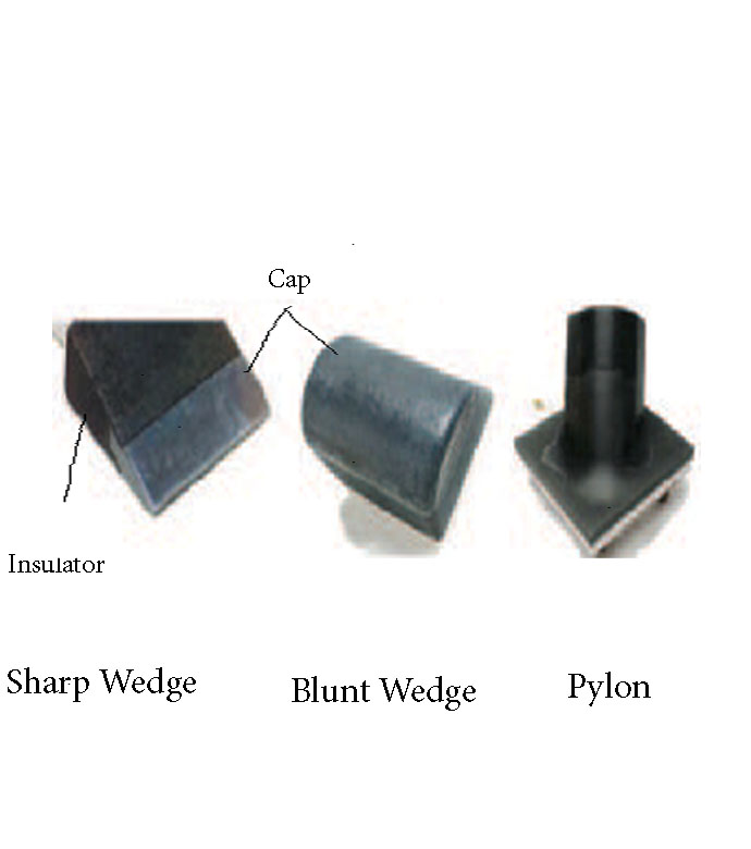
The invention includes an exposed surface cap with a specially formulated coating, an insulator base adjacent to the cap with another specially formulated coating, and one or more pins that extend from the cap through the insulator base to tie the cap and base together through ceramic bonding and mechanical attachment. The cap and insulator base have corresponding depressions and projections that mate and allow for differences in thermal expansion of the cap and base. The cap includes a high-temperature, low density, carbonaceous, fibrous material whose surface is optionally treated with a High Efficiency Tantalum-based Ceramic Composite (HETC) formulation, the fibrous material being drawn from the group consisting of silicon carbide foam and similar porous, high temperature materials. The insulator base and pin(s) contain similar material. The mechanical design is arranged so that thermal expansion differences in the component materials (e.g., cap and insulator base) are easily tolerated. It is applicable to both sharp and blunt leading edge vehicles. This extends the possible application of fibrous insulation to the wing leading edge and/or nose cap on a hypersonic vehicle. The lightweight system comprises a treated carbonaceous cap composed of Refractory Oxidation-resistant Ceramic Carbon Insulation (ROCCI), which provides dimensional stability to the outer mold line, while the fibrous base material provides maximum thermal insulation for the vehicle structure. The composite has graded surface treatments applied by impregnation to both the cap and base. These treatments enable it to survive in an aero-convectively heated environment of high-speed planetary entry. The exact cap and base materials are chosen in combination with modified surface treatments and a specially formulated surface coating, taking into account the duration of exposure and expected surface temperatures for the particular application.


Benefits
- Flight tested
- Survives high heat fluxes 3600 degree F. and above
- Light weight
- Modular, therefore easily replaceable
- Low cost to fabricate and maintain
- Easier to design - can be fabricated and tested in various configurations
- Reusable thermal protection system
- Provides a composite insulating structure
Applications
- Reentry vehicles
- Aircraft
- Spacecraft
- Turbine engines
- Race cars
- Automobiles
- Heating elements for furnaces
- Any application that require thermal protection surfaces
|
Tags:
|
Similar Results

A New Family of Low-Density, Flexible Ablators
The invention provides a family of low density, flexible ablators comprising of a flexible fibrous substrate and a polymer resin. The flexible ablators can withstand a wide range of heating rates (40-540 Watts/cm2) with the upper limit of survivable heat flux being comparable to the survivable heat flux for rigid ablators, such as PICA and Avcoat. The amount and composition of polymer resin can be readily tailored to specific mission requirements. The material can be manufactured via a monolithic approach using versatile manufacturing methods to produce large area heat shields, which provides a material with fewer seams or gaps. The goals of the work are primarily twofold: (i) to develop flexible, ablative Thermal Protection System (TPS) material on a large, blunt shape body which provides aerodynamic drag during hypervelocity atmospheric entry or re-entry, without perishing from heating by the bow shock wave that envelopes the body; and (ii) to provide a relatively inexpensive TPS material that can be bonded to a substrate, that is unaffected by deflections, by differences in thermal expansion or by contraction of a TPS shield, and that is suitable for windward and leeward surfaces of conventional robotic and human entry vehicles that would otherwise employ a rigid TPS shield. This technology produces large areas of heat shields that can be relatively easily attached on the exterior of spacecraft.

Woven Thermal Protection System
Going farther, faster and hotter in space means innovating how NASA constructs the materials used for heat shields. For HEEET, this results in the use of dual-layer, three-dimensional, woven materials capable of reducing entry loads and lowering the mass of heat shields by up to 40%. The outer layer, exposed to a harsh environment during atmospheric entry, consists of a fine, dense weave using carbon yarns. The inner layer is a low-density, thermally insulating weave consisting of a special yarn that blends together carbon and flame-resistant phenolic materials. Heat shield designers can adjust the thickness of the inner layer to keep temperatures low enough to protect against the extreme heat of entering an atmosphere, allowing the heat shield to be bonded onto the structure of the spacecraft itself. The outer and inner layers are woven together in three dimensions, mechanically interlocking them so they cannot come apart. To create this material, manufacturers employ a 3-D weaving process that is similar to that used to weave a 2-D cloth or a rug. For HEEET, computer-controlled looms precisely place the yarns to make this kind of complex three-dimensional weave possible. The materials are woven into flat panels that are formed to fit the shape of the capsule forebody. Then the panels are infused with a low-density version of phenolic material that holds the yarns together and fills the space between them in the weave, resulting in a sturdy final structure. As the size of each finished piece of HEEET material is limited by the size of the loom used to weave the material, the HEEET heat shield is made out of a series of tiles. At the points where each tile connects, the gaps are filled through inventive designs to bond the tiles together.
Printable Heat Shield Formulations Advance Spacecraft Construction
One inner insulative layer, and one outer robust ablative layer comprise the AMTPS technology. When applying the heat shield to the surface of a spacecraft, the insulative layer is printed first and primarily functions to reduce the amount of heat soak into the vehicle. The formulation of the insulative layer has a slightly lower density (as compared to the robust layer) and is adjusted using a differing constituent ratio of phenolic and/or glass microballoon material. Both formulations combine a phenolic resin with various fillers to control pre- and post-cure properties that can be adjusted by varying the carbon and/or glass fiber content along with rheology modifiers to enhance the fluid flow for deposition systems.
The robust layer is applied next and functions as the ablative layer that ablates away or vaporizes when subjected to extremely high temperatures such as those achieved during atmospheric entry. The formulation of the robust layer produces a gas layer as it vaporizes in the extreme heat that acts as a boundary layer. This boundary prevents heat from further penetrating the remaining robust material by pushing away the even hotter shock layer. The shock layer is a region of super-heated compressed gas, positioned in front of the Earth-facing bottom of the spacecraft during atmospheric entry, that results from the supersonic shockwave generated.
Commercial space applications for this AMTPS technology include use on any spacecraft that transits a planetary or lunar atmosphere such as Mars or Saturn’s moon Titan. Additionally, the invention may be useful for launch system rockets to provide heat shielding from atmospheric reentry or to protect ground equipment on the launch pad from rocket exhaust plumes. As the number of government and commercial space missions to primary Earth orbits, the Moon, and the Solar System increase, there will be a growing need for cost-effective, on-demand, and timely fabrication of heat shields for space-related activities.
AMTPS Formulations – Insulative and Robust Variation is at a technology readiness level (TRL) 5 (component and/or breadboard validation in laboratory environment) and is now available for patent licensing. Please note that NASA does not manufacture products itself for commercial sale.

Multilayered Fire Protection System
The Multilayered Fire Protection system uses technology from the space craft flexible heat shield for future planetary missions. By optimizing this material for the fire environment, utilizing heat shield test methods, and experimenting with different materials, the NASA team developed a multilayered fire protection system. This system includes an outer textile layer which reflects over 90 percent of the radiant heat, an insulated layer which protects against convective heat and hot gases, and a non-porous film layer which is a gas barrier layer.

Layered Composite Insulation for Extreme Conditions (LCX)
The approach in developing the LCX system was to provide a combination of advantages in thermal performance, structural capability, and operations. The system is particularly suited for the complex piping, tanks, and apparatus subjected to the ambient environment common in the aerospace industry. The low-cost approach also lends the same technology to industrial applications such as building construction and chilled-water piping. The system can increase reliability and reduce life cycle costs by mitigating moisture intrusion and preventing the resulting corrosion that plagues subambient-temperature insulation systems operating in the ambient (humidity and rain) environment. Accumulated internal water is allowed to drain and release naturally over the systems normal thermal cycles. The thermal insulation system has a long life expectancy because all layer materials are hydrophobic or otherwise waterproof. LCX systems do not need to be perfectly sealed to handle rain, moisture accumulation, or condensation.
Mechanically, the LCX system not only withstands impact, vibration, and the stresses of thermal expansion and contraction, but can help support pipes and other structures, all while maintaining its thermal insulation effectiveness. Conventional insulation systems are notoriously difficult to manage around pipe supports because of the cracking and damage that can occur. Used alone or inside another structure or panel, the LCX layering approach can be tailored to provide additional acoustic or vibration damping as a dual function with the thermal insulating benefits. Because LCX systems do not require complete sealing from the weather, it costs less to install. The materials are generally removable, reusable, and recyclable, a feature not possible with other insulation systems. This feature allows removable insulation covers for valves, flanges, and other components (invaluable benefits for servicing or inspection) to be part of original designs.
Thermal performance of the LCX system has been shown to equal or exceed that of the best polyurethane foam systems, which can degrade significantly during the first two years of operation. With its inherent springiness, the system allows for simpler installation and, more importantly, better thermal insulation because of its consistency and full contact with the cold surface. Improved contact with the cold surface and better closure of gaps and seams are the keys to superior thermal performance in real systems. Eliminating the requirement for glues, sealants, mastics, expansion joints, and vapor barriers provides dramatic savings in material and labor costs of the installed system.


