Search
Aerospace
New Concepts in Film Cooling for Turbine Blades
In one of NASA Glenn's innovations, a shaped recess can be formed on a surface associated with fluid flow. Often V-shaped, this shaped recess can be configured to create or induce fluid effects, temperature effects, or shedding effects. For example, the shaped recess can be paired (upstream or downstream) with a cooling channel. The configuration of the shaped recess can mitigate the lift-off or separation of the cooling jets that are produced by the cooling channels, thus keeping the cooling jets trained on turbine blades and enhancing the effectiveness of the film-cooling process. The second innovation produced to improve film cooling addresses problems that occur when high-blowing ratios, such as those that occur during transient operation, threaten to diminish cooling effectiveness by creating jet detachment. To keep the cooling jet attached to the turbine blade, and also to spread the jet in the spanwise direction, NASA Glenn inventors have successfully used cooling holes that reduce loss by blowing in the upstream direction. In addition, fences may be used upstream of the holes to bend the cooling flow back toward the downstream direction to further reduce mixing losses. These two innovations represent a significant leap forward in making film cooling for turbine blades, and therefore the operation of turbine engines, more efficient.
Optics

Nested Focusing Optics for Compact Neutron Sources
Conventional neutron beam experiments demand high fluxes that can only be obtained at research facilities equipped with a reactor source and neutron optics. However, access to these facilities is limited. The NASA technology uses grazing incidence reflective optics to produce focused beams of neutrons (Figure 1) from compact commercially available sources, resulting in higher flux concentrations. Neutrons are doubly reflected off of a parabolic and hyperbolic mirror at a sufficiently small angle, creating neutron beams that are convergent, divergent, or parallel. Neutron flux can be increased by concentrically nesting mirrors with the same focal length and curvature, resulting in a convergence of multiple neutron beams at a single focal point. The improved flux from the compact source may be used for non-destructive testing, imaging, and materials analysis.
The grazing incidence neutron optic mirrors are fabricated using an electroformed nickel replication technique developed by NASA and the Harvard-Smithsonian Center for Astrophysics (Figure 2). A machined aluminum mandrel is super-polished to a surface roughness of 3-4 angstroms root mean square and plated with layers of highly reflective nickel-cobalt alloy. Residual stresses that can cause mirror warping are eliminated by periodically reversing the anode and cathode polarity of the electroplating system, resulting in a deformation-free surface. The fabrication process has been used to produce 0.5 meter and 1.0 meter lenses.
materials and coatings
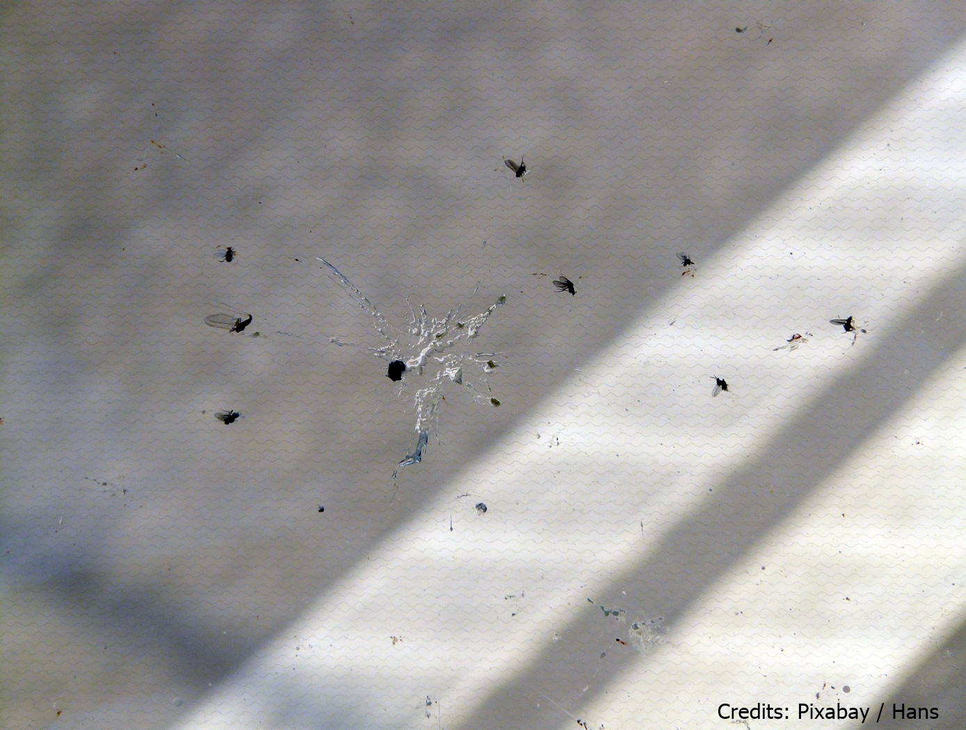
Hydrophobic Epoxy Coating for Insect Adhesion Mitigation
This technology is a copolymeric epoxy coating that is loaded with a fluorinated aliphatic chemical species and nano- to microscale particle fillers. The coating was developed as a hydrophobic and non-wetting coating for aerodynamic surfaces to prevent accumulation of insect strike remains that can lead to natural laminar flow disruption and aerodynamic inefficiencies. The coating achieves hydrophobicity in two ways. First, the fluorinated aliphatic chemical species are hydrophobic surface modification additives that preferentially migrate to the polymer surface that is exposed to air. Secondly, the incorporation of particle fillers produces a micro-textured surface that displays excellent resistance to wetting. Combined, these two factors increase hydrophobicity and can also be used to readily generate superhydrophobic surfaces.
materials and coatings
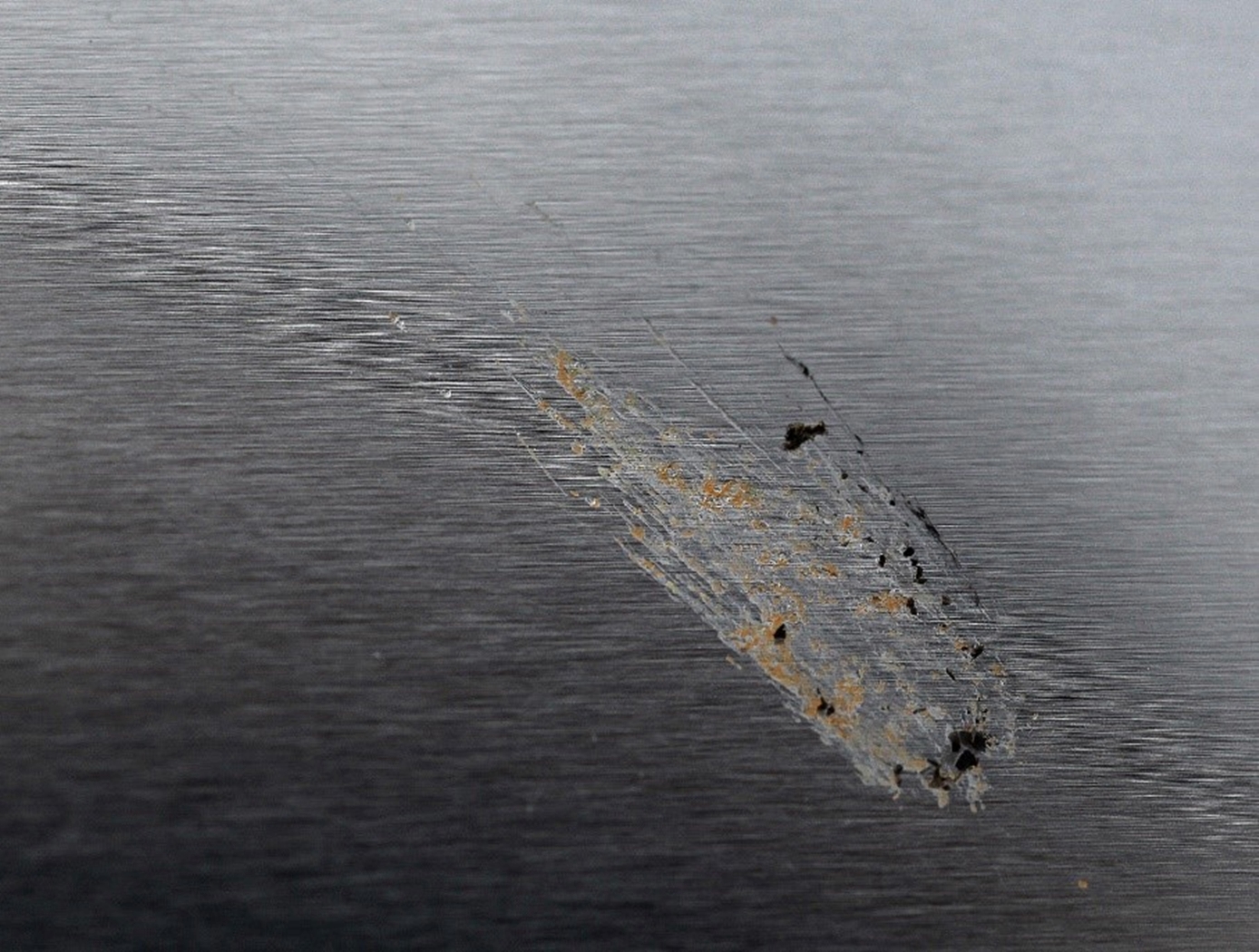
Chemical and Topographical Surface Modifications for Insect Adhesion Mitigation
The technology is a method of mitigating insect residue adhesion to various surfaces upon insect impact. The process involves topographical modification of the surface using laser ablation patterning followed by chemical modification or particulate inclusion in a polymeric matrix. Laser ablation patterning is performed by a commercially available laser system and the chemical spray deposition is composed of nanometer sized silica particles with a hydrophobic solution (e.g. heptadecafluoro-1,1,2,2-tetrahydrodecyltriethoxysilane) in an aqueous ethanol solution. Both topographic and chemical modification of the substrate is necessary to achieve the desired performance.
Materials and Coatings

Silicon Carbide (SiC) Fiber-Reinforced SiC Matrix Composites
Aimed at structural applications up to 2700°F, NASA's patented technologies start with two types of high-strength SiC fibers that significantly enhance the thermo-structural performance of the commercially available boron-doped and sintered small-diameter “Sylramic” SiC fiber. These enhancement processes can be done on single fibers, multi-fiber tows, or component-shaped architectural preforms without any loss in fiber strength. The processes not only enhance every fiber in the preforms and relieve their weaving stresses, but also allow the preforms to be made into more shapes. Environmental resistance is also enhanced during processing by the production of a protective in-situ grown boron-nitride (iBN) coating on the fibers. Thus the two types of converted fibers are called “Sylramic-iBN” and “Super Sylramic-iBN”.
For high CMC toughness, two separate chemical vapor infiltration (CVI) steps are used, one to apply a boron nitride coating on the fibers of the preform and the other to form the SiC-based matrix. The preforms are then heat treated not only to densify and shrink the CVI BN coating away from the SiC matrix (outside debonding), but also to increase its creep resistance, temperature capability, and thermal conductivity.
One crucial advantage in this suite of technologies lies in its unprecedented customizability. The SiC/SiC CMC can be tailored to specific conditions by down-selecting the optimum fiber, fiber coating, fiber architecture, and matrix materials and processes. In any formulation, though, the NASA-processed SiC fibers display high tensile strength and the best creep-rupture resistance of any commercial SiC fiber, with strength retention to over 2700°F.
materials and coatings
Thermal protection supplement for reducing interface thermal mismatch
The invention includes an exposed surface cap with a specially formulated coating, an insulator base adjacent to the cap with another specially formulated coating, and one or more pins that extend from the cap through the insulator base to tie the cap and base together through ceramic bonding and mechanical attachment. The cap and insulator base have corresponding depressions and projections that mate and allow for differences in thermal expansion of the cap and base. The cap includes a high-temperature, low density, carbonaceous, fibrous material whose surface is optionally treated with a High Efficiency Tantalum-based Ceramic Composite (HETC) formulation, the fibrous material being drawn from the group consisting of silicon carbide foam and similar porous, high temperature materials. The insulator base and pin(s) contain similar material. The mechanical design is arranged so that thermal expansion differences in the component materials (e.g., cap and insulator base) are easily tolerated. It is applicable to both sharp and blunt leading edge vehicles. This extends the possible application of fibrous insulation to the wing leading edge and/or nose cap on a hypersonic vehicle. The lightweight system comprises a treated carbonaceous cap composed of Refractory Oxidation-resistant Ceramic Carbon Insulation (ROCCI), which provides dimensional stability to the outer mold line, while the fibrous base material provides maximum thermal insulation for the vehicle structure. The composite has graded surface treatments applied by impregnation to both the cap and base. These treatments enable it to survive in an aero-convectively heated environment of high-speed planetary entry. The exact cap and base materials are chosen in combination with modified surface treatments and a specially formulated surface coating, taking into account the duration of exposure and expected surface temperatures for the particular application.
materials and coatings

High-Temperature Ni-Based Superalloy Composition
NASA's new Ni-based superalloy uses a powder metallurgy (PM) composition that inhibits the deleterious gamma-prime to gamma-phase transformation along stacking faults during high temperature creep deformation. Ni-base superalloys have excellent high temperature properties, mostly due to the presence of coherent precipitates. At higher temperatures, these precipitates are defeated by the diffusional shear dislocations producing intrinsic and extrinsic faults. Recent studies have found that, during deformation of turbine disk alloys at high temperature, Co, Cr, and Mo segregate to these faults (removing Ni and Al) inside the strengthening precipitates of these alloys. This represents a local phase transformation from the strengthening precipitate to the weaker matrix phase. Therefore, this elemental segregation significantly weakens the ability of a precipitate to withstand further deformation, producing faster strain rates in the alloy at higher temperatures. This invention presents a solution to prevent this type of segregation along these two faults to improve the creep properties of turbine disks and similar Ni-based alloys. By alloying a specific amount of eta phase formers (Ti, Ta, Nb, and Hf), the phase transformation to can be eliminated along 2-layer extrinsic stacking faults (SESFs) in precipitates without precipitating bulk eta phase. Also, by adding a certain amount of D019 formers (Mo and W), the phase transformation to can be mitigated along 1-layer intrinsic stacking faults (SISFs) without producing bulk sigma phase. This alloy composition incorporates both strengthening methods for use in jet turbine disks, though the composition has applications in other high-stress and/or high-temperature environments as are found in power plants, space launch systems, and other critical structural applications.
information technology and software
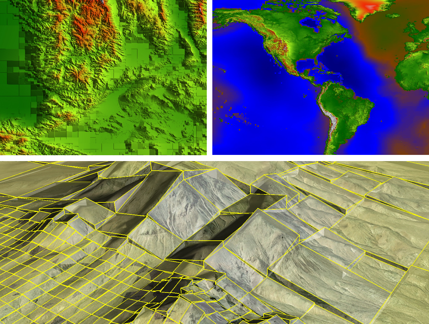
Real-Time, High-Resolution Terrain Information in Computing-Constrained Environments
NASA Armstrong collaborated with the U.S. Air Force to develop algorithms that interpret highly encoded large area terrain maps with geographically user-defined error tolerances. A key feature of the software is its ability to locally decode and render DTMs in real time for a high-performance airplane that may need automatic course correction due to unexpected and dynamic events. Armstrong researchers are integrating the algorithms into a Global Elevation Data Adaptive Compression System (GEDACS) software package, which will enable customized maps from a variety of data sources.
<strong>How It Works</strong>
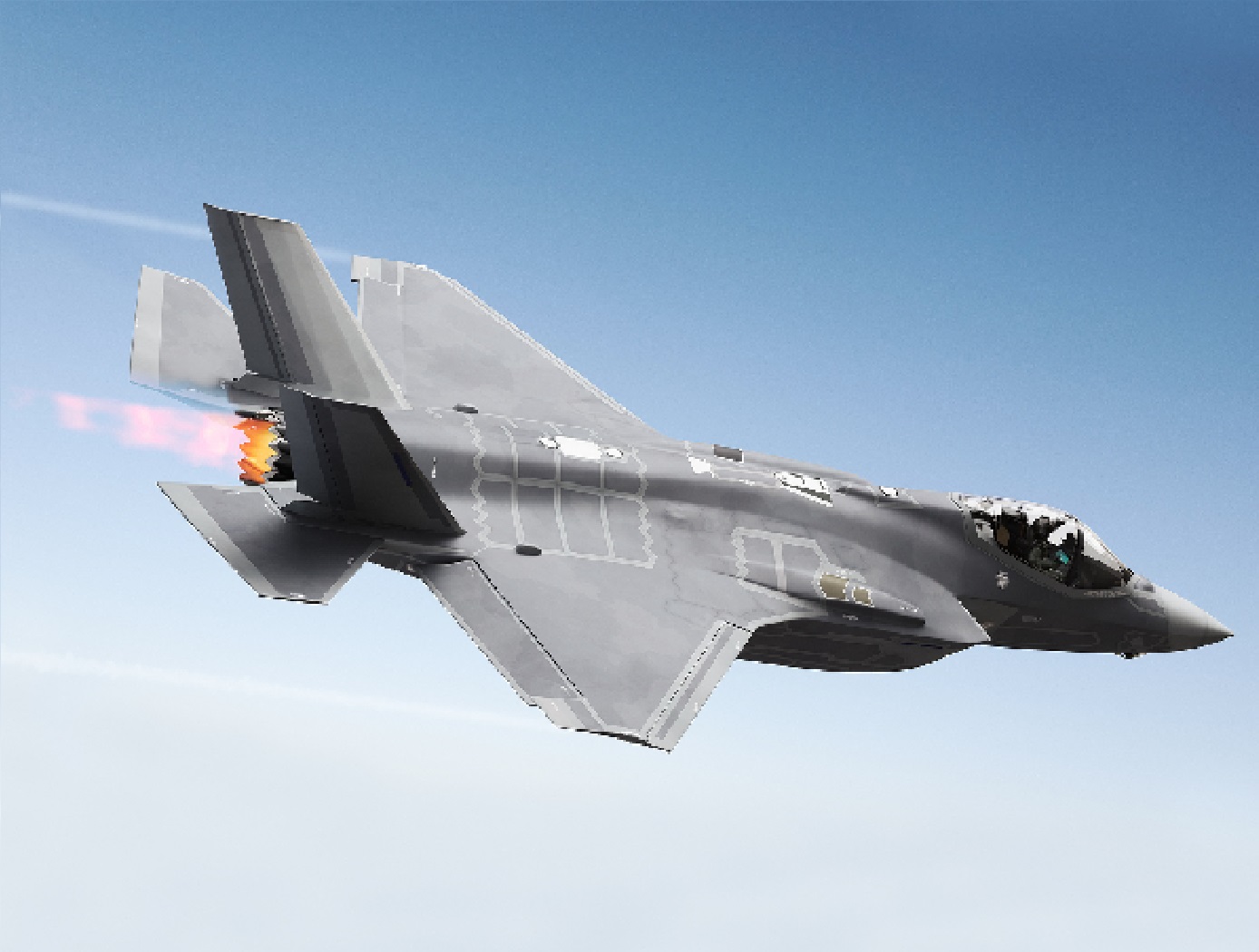
The DTM software achieves its high performance encoding and decoding processes using a unique combination of regular and semi-regular geometric tiling for optimal rendering of a requested map. This tiling allows the software to retain important slope information and continuously and accurately represent the terrain. Maps and decoding logic are integrated into an aircraft's existing onboard computing environment and can operate on a mobile device, an EFB, or flight control and avionics computer systems. Users can adjust the DTM encoding routines and error tolerances to suit evolving platform and mission requirements. Maps can be tailored to flight profiles of a wide range of aircraft, including fighter jets, UAVs, and general aviation aircraft.
The DTM and GEDACS software enable the encoding of global digital terrain data into a file size small enough to fit onto a tablet or other handheld/mobile device for next-generation ground collision avoidance. With improved digital terrain data, aircraft could attain better performance. The system monitors the ground approach and an aircraft's ability to maneuver by predicting several multidirectional escape trajectories, a feature that will be particularly advantageous to general aviation aircraft.
<strong>Why It Is Better</strong>
Conventional DTM encoding techniques used aboard high-performance aircraft typically achieve relatively low encoding process ratios. Also, the computational complexity of the decoding process can be high, making them unsuitable for the real-time constrained computing environments of high-performance aircraft. Implementation costs are also often prohibitive for general aviation aircraft. This software achieves its high encoding process ratio by intelligently interpreting its maps rather than requiring absolute retention of all data. For example, the DTM software notes the perimeter and depth of a mining pit but ignores contours that are irrelevant based on the climb and turn performance of a particular aircraft and therefore does not waste valuable computational resources. Through this type of intelligent processing, the software eliminates the need to maintain absolute retention of all data and achieves a much higher encoding process ratio than conventional terrain-mapping software. The resulting exceptional encoding process allows users to store a larger library of DTMs in one place, enabling comprehensive map coverage at all times. Additionally, the ability to selectively tailor resolution enables high-fidelity sections of terrain data to be incorporated seamlessly into a map.
Materials and Coatings
Enhanced Software Suite Maximizes Non-Destructive Evaluation (NDE) Methods
This technology provides comprehensive, detailed, and accurate NDE detection and characterization of subsurface defects in composites and some metallic hardware. This complete software suite normalizes and calibrates the data, which provides more stable measurements and reduces the occurrence of errors due to the operator and to camera variability.
When using flash IR thermography to evaluate materials, variations in the thermal diffusivity of the material manifest themselves as anomalies in the IR image of the test surface. Post-processing of this raw IR camera data provides highly detailed analysis of the size and characterization of anomalies. The newly incorporated Transient and Lock-In Thermography methods allow the analysis of thicker material and with better flaw resolution than Flash Thermography alone.
The peak contrast and peak contrast time profiles generated through this analysis provide quantitative interpretation of the images, including detailed information about the size and shape of the anomalies. The persistence energy and persistence time profiles provide highly sensitive data for detected anomalies. Peak contrast, peak time, persistence time, and persistence energy measurements also enable monitoring for flaw growth and signal response to flaw size analysis.
This technology is at a technology readiness level (TRL) of 7 (system prototype demonstration in an operational environment), and the innovation is now available for your company to license. Please note that NASA does not manufacture products itself for commercial sale.

