Search
PATENT PORTFOLIO

Deployed Electromagnetic Radiation Deflector Shield
The typical remedy for space radiation hazards has been to harden the space vehicle's electronics and software from these high-speed particles and placing heavy shielding in these manned or sensitive areas. This adds considerable weight and cost to the launch vehicle, reduces payload capacity, and is passive in nature. SEPs and CMEs can be deflected by a magnetic field to pass around the spacecraft and not be absorbed by it. This deflection of solar wind and radiation is due to the Lorentz force. However, a magnetic field that is attached to the spacecraft and enclosing it would cause other shielding issues with equipment and would require much more electrical power to operate due to the need to enclose the entire spacecraft within that attached magnetic field.
This would also perturb the data collection and transmissions of the spacecraft. Additionally, the generated magnetic field can capture some of the solar radiation as a plasma within the magnetic torus further impeding scientific data collection due to its close position to the spacecraft.
DERDS is deployed in space away from the protected spacecraft to remain between the radiation source and the spacecraft. It utilizes on board cosmic ray sensors to note the need for the strength of the magnetic field, and on-board sensors to position itself directly in line between the radiation source and the protected spacecraft or station. Onboard computers and thrusters maintain the required position, so that the magnetic field is positioned for the best deflection angle based on incoming radiation. The DERDS magnetic field can be varied in both direction, intensity, and time by use of both AC and DC electrical power inputs and varied as needed to optimize the deflection angle and power requirements. The magnetic field can also be perturbed in irregular or set patterns by onboard computers and sensors as needed to maintain the proper deflection of SEPs, CMEs, and other cosmic rays. DERDS creates a magnetic field that will not need to be so large (with a much larger power requirement) as to encompass the entire protected spacecraft, and the magnetic field will not interfere with the spacecraft.
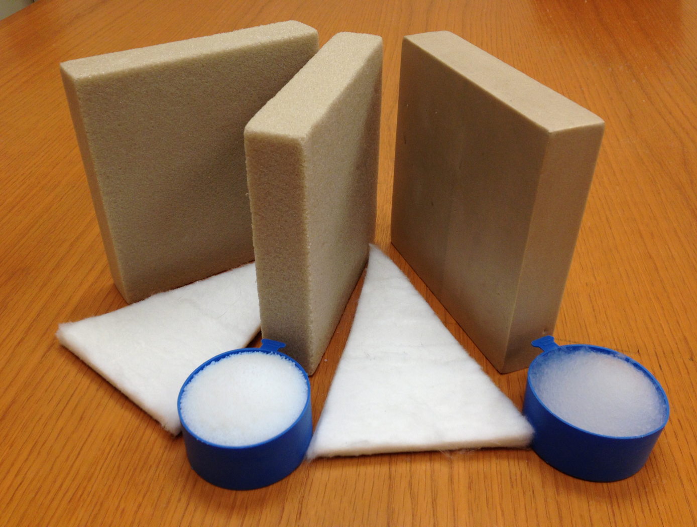
Aerofoam
The Aerofoam composites have superior thermal and acoustic insulation properties when compared to conventional polyimide foams. In addition, they provide greater structural integrity than the fragile aerogel materials can provide independently. In general, polymer foams can provide excellent thermal insulation, and polyimide foams have the additional advantage of excellent high-temperature behavior and flame resistance compared to other polymer systems (they do not burn or release noxious chemicals). Incorporating aerogel material into the polyimide foam as described by this technology creates a composite that has been demonstrated to provide additional performance gains, including 25% lower thermal conductivity with no compromise of the structural integrity and high-temperature behavior of the base polyimide foam. The structural properties of Aerofoam are variable based on its
formulation, and it can be used in numerous rigid and flexible foams of varying densities.
Aerofoam has a number of potential commercial applications, including construction, consumer appliances, transportation, electronics, healthcare, and industrial equipment. In addition, these high-performance materials may prove useful in applications that require insulation that can withstand harsh environments, including process piping, tanks for transporting and storing hot or cold fluids, ship and boat building, and aerospace applications.
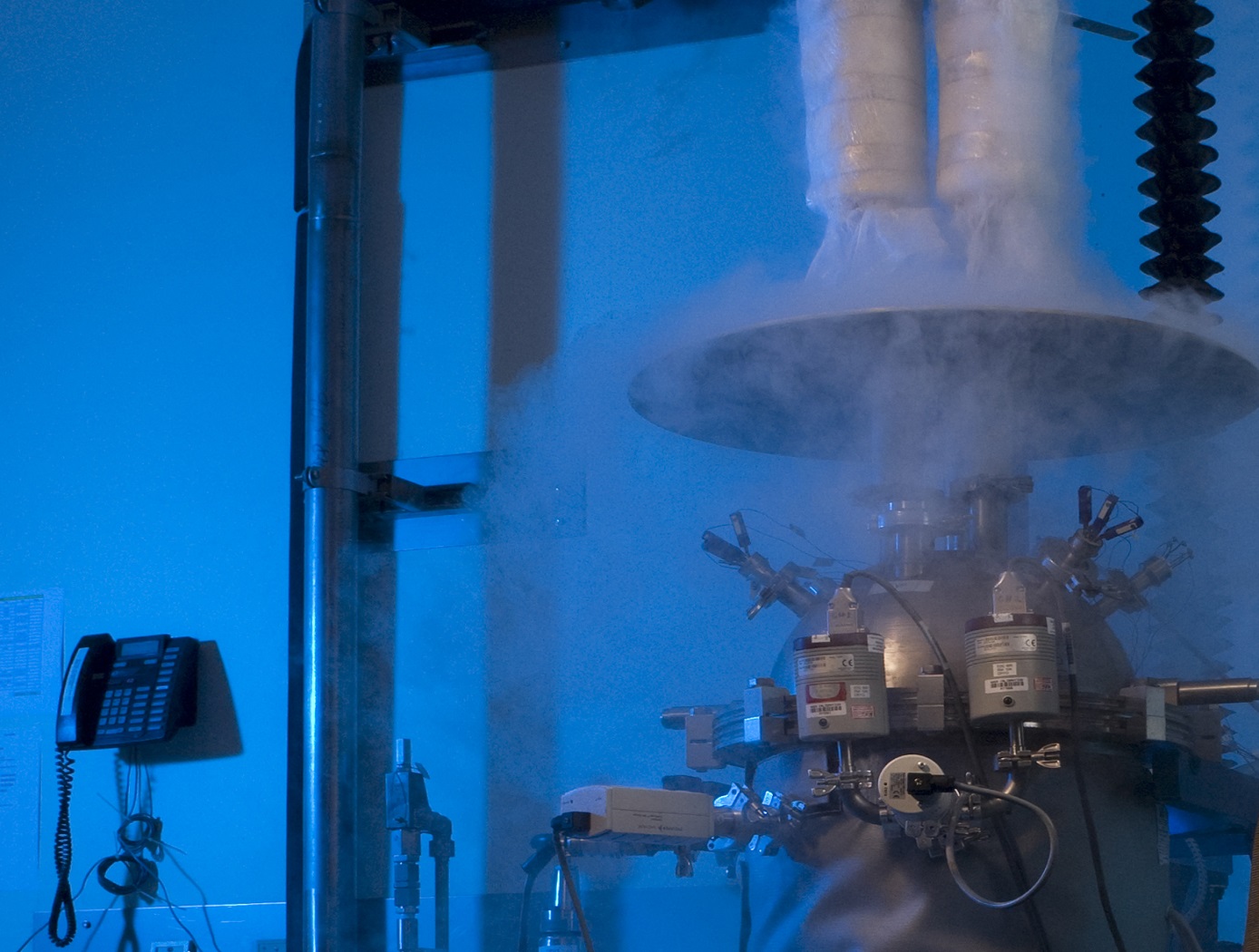
Cryostat-100
Cryostat-100 combines the best features of previous cryostats developed by NASA, while offering new features and conveniences. This unit can readily handle the full range of cryogenic-vacuum conditions over several orders of magnitude of heat flux. Guide rings, handling tools, and other design items make insulation change-out and test measurement verification highly reliable and efficient to operate. The new apparatus requires less ancillary equipment (it is not connected to storage tank, phase separator, subcooler, etc.) to operate properly. It is top-loading, which makes disassembly, change-out, and instrumentation hook-up much faster. The thermal stability is improved because of internal vapor plates, a single-tube system of filling and venting, bellows feed-throughs, Kevlar thread suspensions, and heavy-wall stainless-steel construction.
The cold mass of Cryostat-100 is 1m long, with a diameter of 168 mm. The test articles can therefore be of a corresponding length and diameter, with a nominal thickness of 25.4 mm. Shorter lengths are acceptable, and thicknesses may be from 0 mm to 50 mm. Tests are conducted from ambient pressure (760 torr) to high vacuum (below 110-4 torr) and at any vacuum pressure increment between these two extremes. The residual gas (and purge gas) is typically nitrogen but can be any purge gas, such as helium, argon, or carbon dioxide.
Typically, eight cold vacuum pressures are performed for each test series. The warm boundary temperature is approximately 293 K, and the cold boundary temperature is approximately 78 K. The delta temperature for the cryogenic testing is therefore approximately 215 K. A unique lift mechanism provides for change-out of the insulation test specimens. It also provides for maintenance and other operations in the most effective and time-efficient ways. The lift mechanism is also a key to the modularity of the overall system.
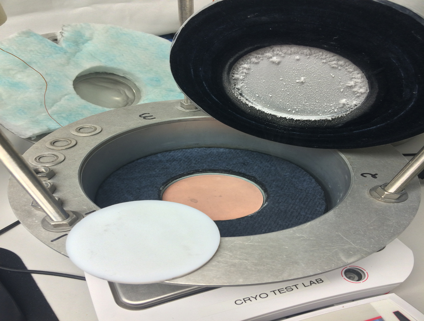
Macroflash (Cup Cryostat)
Advances in new polymers and composites along with growing industrial needs in below-ambient temperature applications have brought about the Macroflash development. Accurate thermal performance information, including effective thermal conductivity data, are needed under relevant end-use conditions. The Macroflash is a practical tool for basic testing of common materials or research evaluation of advanced materials/systems.
The Macroflash can test solids, foams, or powders that are homogeneous or layered in composition. Test specimens are typically 75mm in diameter and 6mm in thickness. The cold side is maintained by liquid nitrogen at 77 K while a heater disk maintains a steady warm-side temperature from ambient up to 373 K. The steady boiloff of the liquid nitrogen provides a direct measure of the heat energy transferred through the thickness of the test specimen. Nitrogen or other gas is supplied to the instrument to establish a stable, moisture-free, ambient pressure environment. Different compression loading levels can also be conveniently applied to the test specimen as needed for accurate, field-representative thermal performance data. The Macroflash is calibrated from approximately 10 mW/m-K to 800 mW/m-K using well-characterized materials.
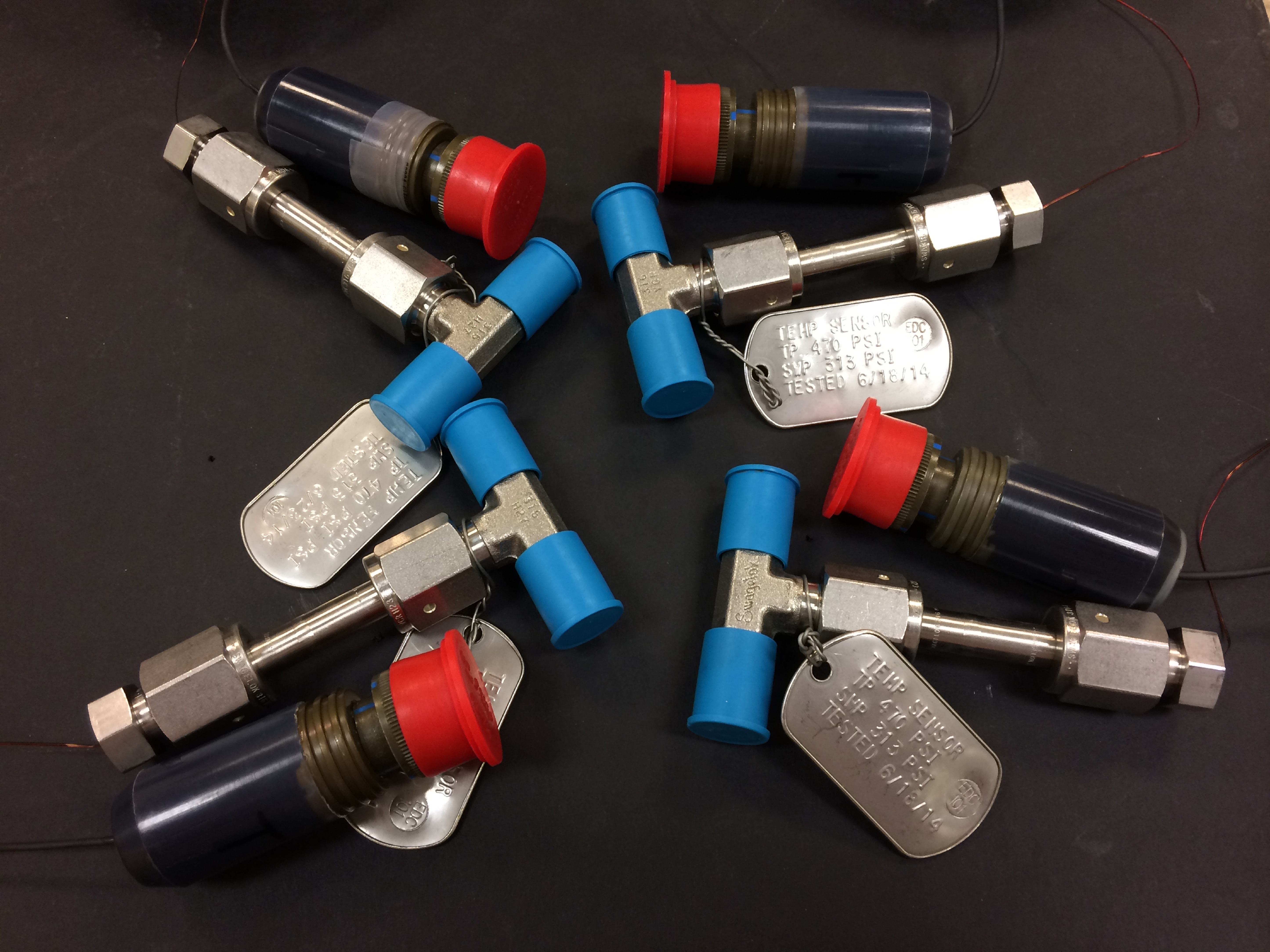
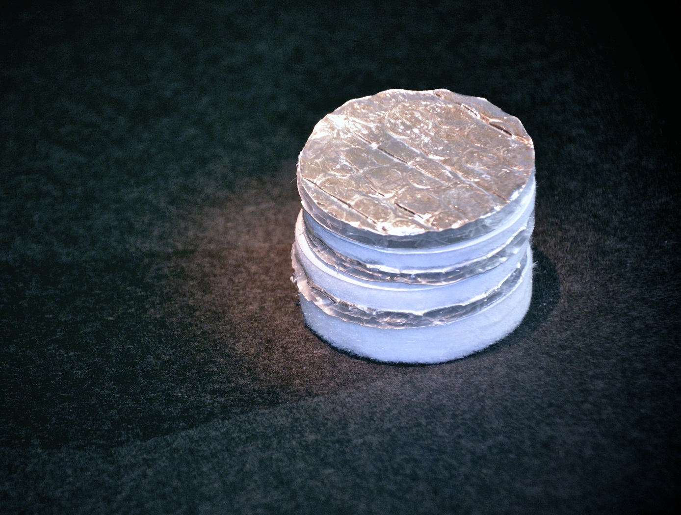
Feedthrough for Severe Environments and Temperatures
Space and ground launch support related hardware often operate under extreme pressure, temperature, and corrosive conditions. When dealing with this type of equipment, it is frequently necessary to run wiring, tubes, or fibers through a barrier separating one process from another with one or both operating in extreme environments. Feedthroughs used to route the wiring, tubes, or fibers through these barriers must meet stringent sealing and leak tightness requirements.
This affordable NASA feedthrough meets or exceeds all sealing and leak requirements utilizing easy-to-assemble commercial-off-the-shelf hardware with no special tooling. The feedthrough is a fully reconfigurable design; however, it can also be produced as a permanent device. Thermal cycling and helium mass spectrometer leak testing under extreme conditions of full cryogenic temperatures and high vacuum have proven the sealing capability of this feedthrough with or without potting (epoxy fill) on the ends. Packing material disks used in the construction of the device can be replaced as needed for rebuilding a given feedthrough for another job or a different set of feeds if potting is not used for the original feedthrough build. (Potting on one or both sides of the sleeve provides double or triple leak sealing protection). Variable Compression Ratio (VCR) connectors were adapted for the pressure seal on the feedthrough; however, any commercial connector can be similarly adapted. The design can easily be scaled up to larger (2" diameter) and even very large (12" or more) sizes.

Flexible Body Control Using Fiber Optic Sensors (FlexFOS)
Aerospace vehicles experience flexible dynamics that have adverse effects on guidance, navigation, and control. Vehicles that include automated control are further affected by flexible modes and structural vibrations. Flexible dynamics become even more critical as demand for larger and more fuel efficient vehicles increases.
Using fiber optic technology to collect both flexible and rigid body information enables increased knowledge (data) of the state of a vehicle, a more robust collection method against weather conditions, and a more cost-effective measurement method. This technology could potentially be applied to aerospace vehicles as well as commercial space structures, commercial aerospace structures, cranes, buildings, or bridges - anything with a large cross sectional ratio.
The RSS is the key to developing a sensor which provides flexible body kinematics. A reference structure must be chosen that minimizes weight impacts while retaining structural integrity. The reference structure material must also be very predictable and repeatable. Once this geometry has been optimized, analyzed, and mapped it is integrated with strain sensors making it a Reference Strain Structure. The RSS must then be integrated into an adaptive structure, which both protects and provides a connection to the desired structure to be measured.
The RSS combined with the properly designed algorithms provides the capability and portability to be installed on any of the aforementioned structures alleviating unique engineering and calibration required for each structure or vehicle. It also provides the capability to employ actuators to counteract the effects of structural vibrations. FlexFOS provides a simple, portable solution adaptable to any structure.
Layered Composite Insulation for Extreme Conditions (LCX)
The approach in developing the LCX system was to provide a combination of advantages in thermal performance, structural capability, and operations. The system is particularly suited for the complex piping, tanks, and apparatus subjected to the ambient environment common in the aerospace industry. The low-cost approach also lends the same technology to industrial applications such as building construction and chilled-water piping. The system can increase reliability and reduce life cycle costs by mitigating moisture intrusion and preventing the resulting corrosion that plagues subambient-temperature insulation systems operating in the ambient (humidity and rain) environment. Accumulated internal water is allowed to drain and release naturally over the systems normal thermal cycles. The thermal insulation system has a long life expectancy because all layer materials are hydrophobic or otherwise waterproof. LCX systems do not need to be perfectly sealed to handle rain, moisture accumulation, or condensation.
Mechanically, the LCX system not only withstands impact, vibration, and the stresses of thermal expansion and contraction, but can help support pipes and other structures, all while maintaining its thermal insulation effectiveness. Conventional insulation systems are notoriously difficult to manage around pipe supports because of the cracking and damage that can occur. Used alone or inside another structure or panel, the LCX layering approach can be tailored to provide additional acoustic or vibration damping as a dual function with the thermal insulating benefits. Because LCX systems do not require complete sealing from the weather, it costs less to install. The materials are generally removable, reusable, and recyclable, a feature not possible with other insulation systems. This feature allows removable insulation covers for valves, flanges, and other components (invaluable benefits for servicing or inspection) to be part of original designs.
Thermal performance of the LCX system has been shown to equal or exceed that of the best polyurethane foam systems, which can degrade significantly during the first two years of operation. With its inherent springiness, the system allows for simpler installation and, more importantly, better thermal insulation because of its consistency and full contact with the cold surface. Improved contact with the cold surface and better closure of gaps and seams are the keys to superior thermal performance in real systems. Eliminating the requirement for glues, sealants, mastics, expansion joints, and vapor barriers provides dramatic savings in material and labor costs of the installed system.
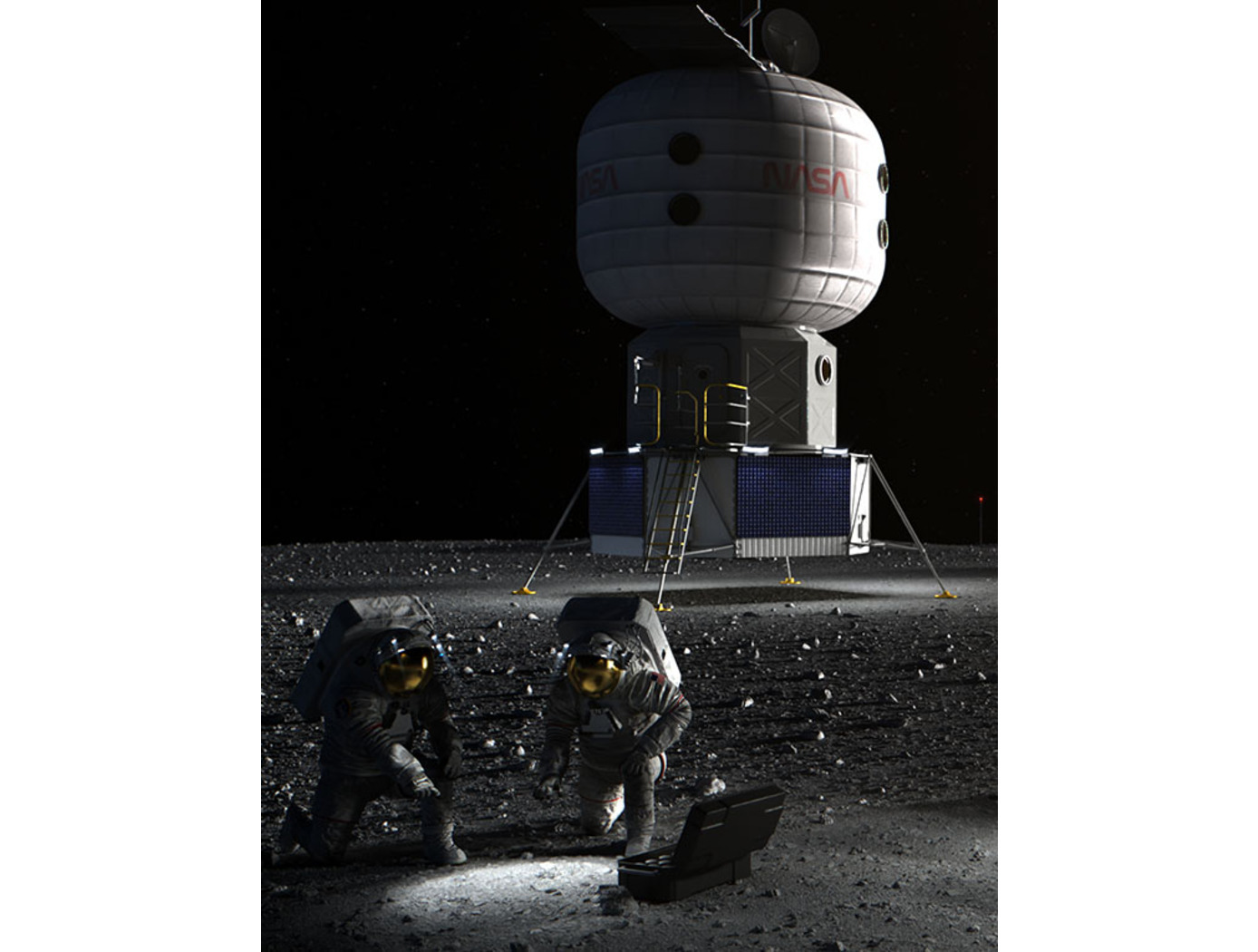
Regolith-Polymer 3D Printing
The invention consists of a 3D print head apparatus that heats and extrudes a regolith-polymer (or other) mixture as part of an additive manufacturing process. The technology includes a securing mechanism, hopper, nozzle, barrel, and heating system. The securing mechanism attaches to a wrist joint of a robotic arm. The hopper, connected to the securing mechanism, has a cavity and a lower aperture. The barrel is an elongated, hollow member with its first end connected to the hopper's lower aperture and its second end connected to the nozzle's upper aperture. The heating system is positioned along the barrel and comprises a heater, thermocouple, insulator, and heating controller. The heating controller activates the heater based on input signals received from the thermocouple.
The print head apparatus also includes a feed screw, drive shaft, and motor. The feed screw is positioned within the elongated hollow member of the barrel, and the drive shaft transmits torque to the feed screw. The motor provides torque to the drive shaft.
An agitator is secured to the drive shaft, facilitating the consistent movement and mixing of the regolith-polymer mixture in the hopper. The nozzle includes a tube with an open end and an occluded end, allowing the mixture to be extruded through the lower aperture.
The jointly developed 3D print head technology enables efficient, large-scale additive construction using in-situ resources, such as regolith or other materials. The innovation reduces the need for transporting materials from Earth and allows for sustainable habitat development on the Moon or Mars. Given its adaptability to different crushed rock-polymer materials, the invention may also serve as an alternative to conventional Portland concrete construction on Earth.
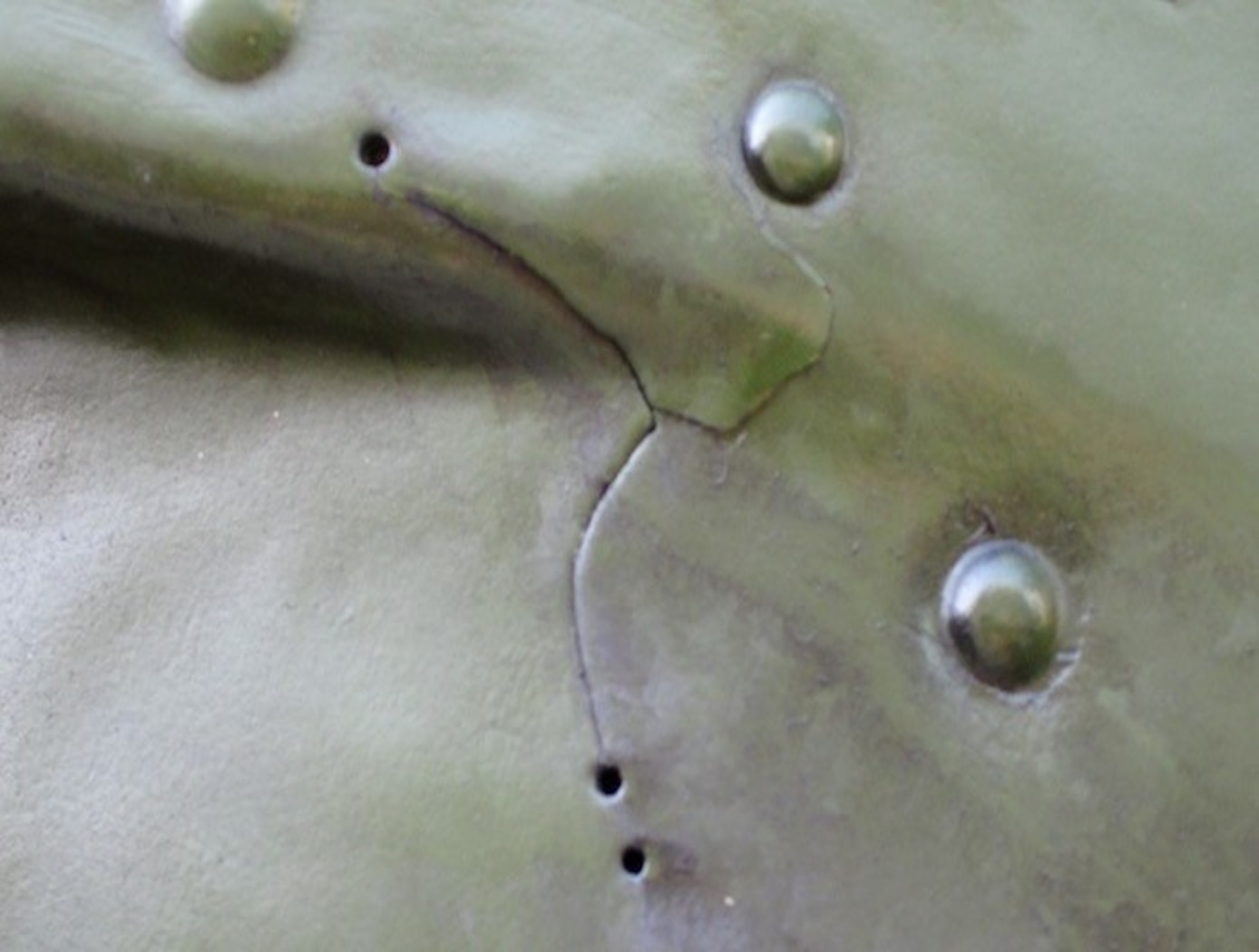
Self-Healing Aluminum Metal Matrix Composite (MMC)
This materials system is comprised of an Al metal matrix with high-performance SMA reinforcements. The combination of the unique matrix composition and SMA elements allow for this material system to self-repair via a two-step crack repair method. When a crack is present in the matrix material, the MMC is heated above the SMA's austenite start (As) temperature. This initiates shape recovery of the SMA, pulling the crack together as the SMA reinforcements return to their initial length. Concurrently, the increased temperature causes softening and liquefaction of the eutectic micro-constituent in the matrix, which enables the recovery of plastic strain in the matrix as well as crack filling. Combined with the crack closure force provided by the SMA reinforcements completely reverting to their original length, the MMC welds itself together and, upon cooling, results in a solidified composite able to realize its pre-cracked, original strength. The research team has demonstrated and tested the new materials. The team induced cracks in prototype materials based on Al-Si matrix with SMA (NiTi) reinforcements and demonstrated the recovery of tensile strength after healing. Data from tensile and fatigue tests of the samples before and after the fatigue crack healing shows a 91.6% healing efficiency on average under tensile conditions.
View more patents

