Search
PATENT PORTFOLIO
Optics
If you're looking for the most advanced optics technology available, look no further than NASA's extensive portfolio. From high-precision imaging systems to state-of-the-art lasers and optical components, NASA's optics technologies can help revolutionize a wide range of industries and drive the next generation of innovation.

Optical Head-Mounted Display System for Laser Safety Eyewear
The system combines laser goggles with an optical head-mounted display that displays a real-time video camera image of a laser beam. Users are able to visualize the laser beam while his/her eyes are protected. The system also allows for numerous additional features in the optical head mounted display such as digital zoom, overlays of additional information such as power meter data, Bluetooth wireless interface, digital overlays of beam location and others. The system is built on readily available components and can be used with existing laser eyewear. The software converts the color being observed to another color that transmits through the goggles. For example, if a red laser is being used and red-blocking glasses are worn, the software can convert red to blue, which is readily transmitted through the laser eyewear. Similarly, color video can be converted to black-and-white to transmit through the eyewear.
Reflection-Reducing Imaging System for Machine Vision Applications
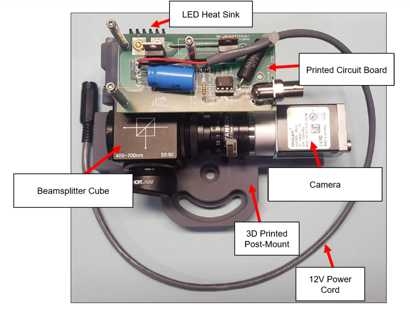
NASA’s imaging system is comprised of a small CMOS camera fitted with a C-mount lens affixed to a 3D-printed mount. Light from the high-intensity LED is passed through a lens that both diffuses and collimates the LED output, and this light is coupled onto the cameras optical axis using a 50:50 beam-splitting prism.
Use of the collimating/diffusing lens to condition the LED output provides for an illumination source that is of similar diameter to the camera’s imaging lens. This is the feature that reduces or eliminates shadows that would otherwise be projected onto the subject plane as a result of refractive index variations in the imaged volume. By coupling the light from the LED unit onto the camera’s optical axis, reflections from windows – which are often present in wind tunnel facilities to allow for direct views of a test section – can be minimized or eliminated when the camera is placed at a small angle of incidence relative to the window’s surface. This effect is demonstrated in the image on the bottom left of the page.
Eight imaging systems were fabricated and used for capturing background oriented schlieren (BOS) measurements of flow from a heat gun in the 11-by-11-foot test section of the NASA Ames Unitary Plan Wind Tunnel (see test setup on right). Two additional camera systems (not pictured) captured photogrammetry measurements.
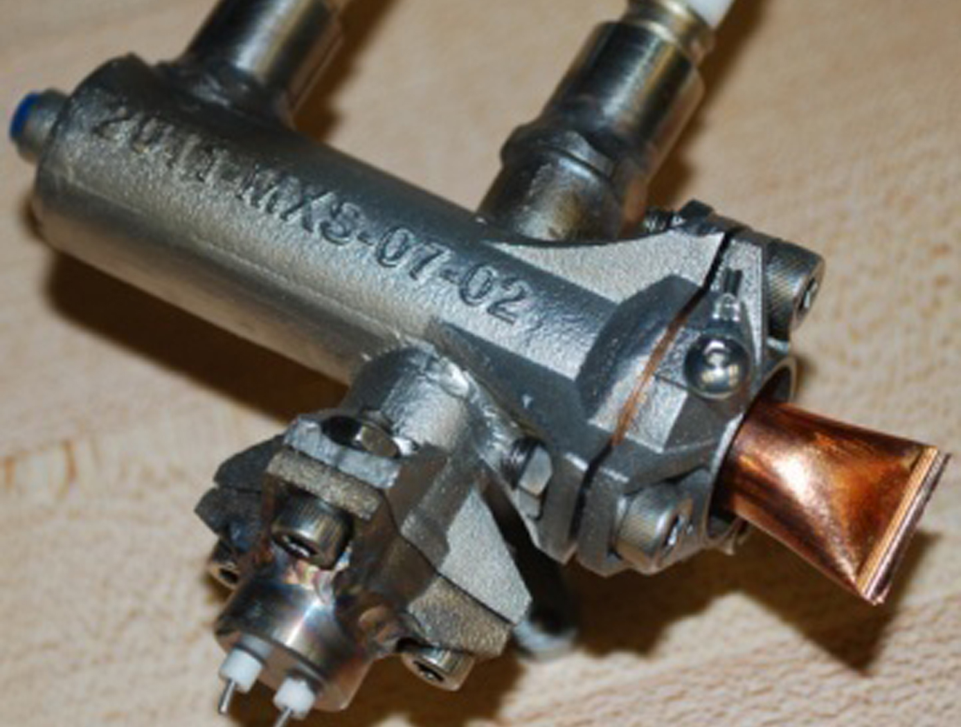
Miniaturized High-Speed Modulated X-Ray Source (MXS)
The MXS produces electrons by shining UV light from an LED onto a photocathode material such as magnesium. The electrons are then accelerated across several kV and into a chosen target material; deceleration produces X-rays characteristic of the target. The MXS uses an electron multiplier for high X-ray production efficiency.
The MXS is more compact, rugged, and power-efficient than standard X-ray sources. It can be manufactured using commercially available components and 3D printed housing, resulting in a low cost to manufacture. Unlike traditional X-ray sources, the MXS does not require a filament or vacuum and cooling systems. Most importantly, enabling rapid and arbitrary modulation allows using X-rays in the time domain, a new dimension to X-ray applications.
Self-Phase-Locked Distributed Gain Laser Architecture
NASA Goddard Space Flight Center has developed a laser architecture to coherently combine energy from spatially distributed gain sources. Using a combination of lenslet arrays (to split and combine separate beams) or diffractive optical elements, each source can be phase-matched into an effective single source.

Video Acuity Measurement System
The Video Acuity metric is designed to provide a unique and meaningful measurement of the quality of a video system. The automated system for measuring video acuity is based on a model of human letter recognition. The Video Acuity measurement system is comprised of a camera and associated optics and sensor, processing elements including digital compression, transmission over an electronic network, and an electronic display for viewing of the display by a human viewer. The quality of a video system impacts the ability of the human viewer to perform public safety tasks, such as reading of automobile license plates, recognition of faces, and recognition of handheld weapons. The Video Acuity metric can accurately measure the effects of sampling, blur, noise, quantization, compression, geometric distortion, and other effects. This is because it does not rely on any particular theoretical model of imaging, but simply measures the performance in a task that incorporates essential aspects of human use of video, notably recognition of patterns and objects. Because the metric is structurally identical to human visual acuity, the numbers that it yields have immediate and concrete meaning. Furthermore, they can be related to the human visual acuity needed to do the task. The Video Acuity measurement system uses different sets of optotypes and uses automated letter recognition to simulate the human observer.

On-demand, Dynamic Reconfigurable Broadcast Technology for Space Laser Communication
NASA Goddard Space Flight Center has developed a configurable phase mirror system that can address likely obstacles in space optical communications. Through using miniature adjustable mirrors and programmed phase delays to diffract a single communication beam, numerous diffracted beams can be sent to other satellites in various directions for communication and tracking. The initial laser beams wave profile can be dynamically regulated through a fast Fourier transform (FFT) so that when it reaches its desired destination, it forms an intended illuminated spot at the target satellite. Since all the diffracted beams share the same phase mirror, the antenna gain needed to broadcast these beams does not require a multiplied aperture.

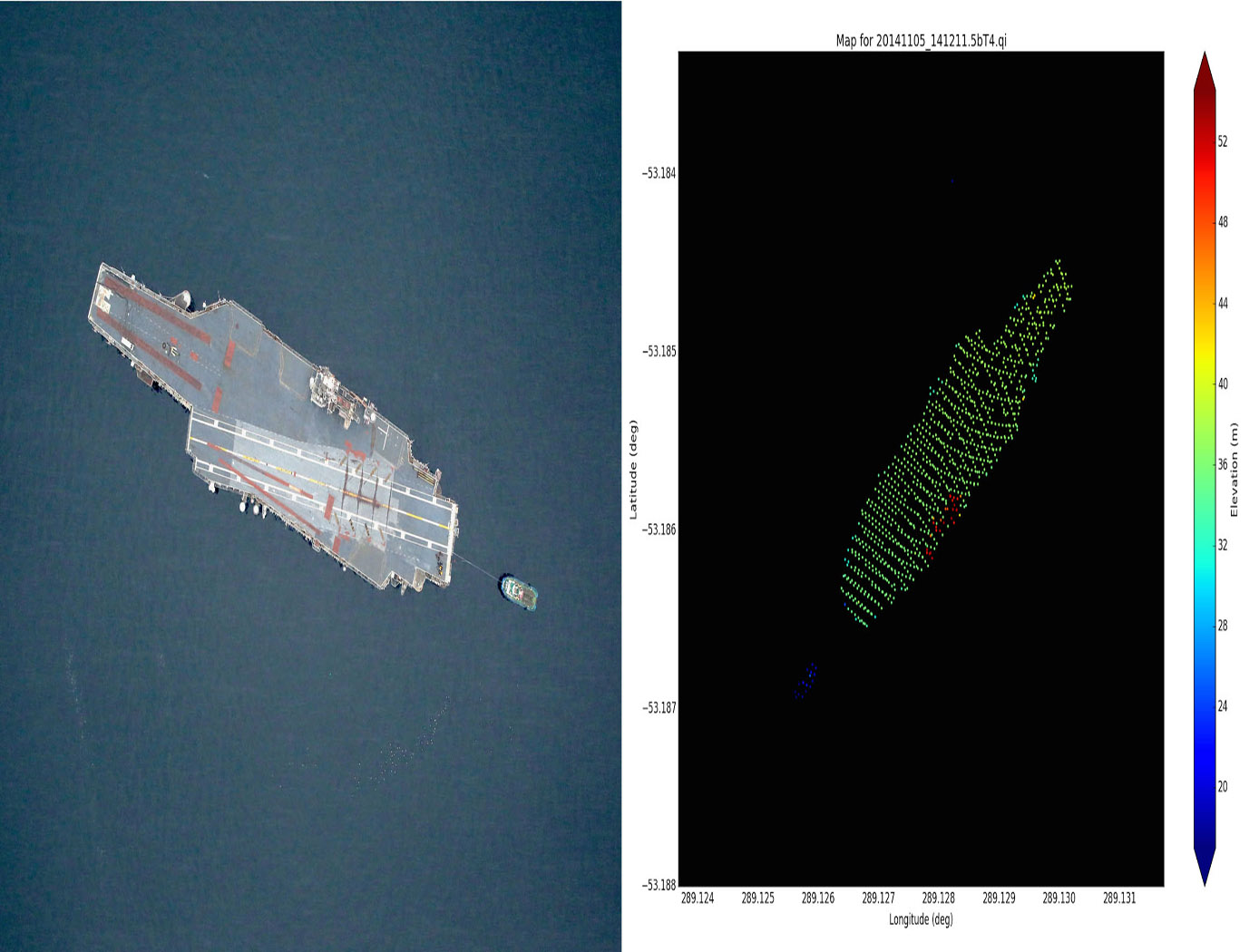
Digital Beamforming Interferometry
NASA Goddard Space Flight Center (GSFC) has developed a new approach that uses a single phased array antenna and a single pass configuration to generate interferograms, known as Digital Beamforming Interferometry. A digital beamforming radar system allows the implementation of non-conventional radar techniques, known as Digital Beamforming Synthetic Aperture Radar Multi-mode Operation (DBSAR).
DBSAR is an L-Band airborne radar that combines advanced radar technology with the ability to implement multimode remote sensing techniques, including several variations of SAR, scatterometry over multiple beams, and an altimeter mode. The Multiple channel data acquired with a digital beamformer systems allows the synthesis of beams over separate areas of the antenna, effectively dividing the single antenna into two antennas. The InSAR technique is then achieved by generating interferograms from images collected with each of the antennas. Since the technique is performed on the data, it allows for synthesizing beams in different directions (or look angles) and performs interferometry over large areas.
Digital Beamforming Interferometry has potential in many areas of radar applications. For example, NASA GSFC innovators developed the first P-Band Digital Beamforming Polarimetric Interferometric SAR Instrument to measure ecosystem structure, biomass, and surface water.
Kodiak 3D Lidar
NASA Goddard Space Flight Center has developed a 3D lidar system that consists of microelectromechanical systems (MEMS) beam steering, high performance reconfigurable computing, and an in-depth understanding of systems level integration. Kodiak combines a 3D MEMS scanning lidar with a long range narrow FOV telescope to produce a flexible and capable space flight ranging system. Also included is SpaceCube-level processing power to host a variety of algorithms enabling sensing and 6 degrees of freedom.

Micro non-planar ring oscillator (micro-NPRO
NASA Goddard Space Flight Center has developed a specifically shaped, smaller NPRO using a higher-doped Neodymium (Nd) crystal, helping to stabilize spatial modes and removing problems in frequency and polarization. This NPRO eliminates a technology gap between micro-chip lasers and traditional NPROs.
View more patents

