Search
Communications
Lightweight, Self-Deployable Helical Antenna
NASA's newly developed antenna is lightweight (at or below 2 grams), low volume (at or below 1.2 cm3), and low stowage thickness (approx. 0.7 mm), all while delivering high performance (at or above 10 dBi gain). The antenna includes a novel design-material combination in a helical coil conformation. The design allows the antenna to compress for stowage (e.g., satellite launch), then self-deploy at the desired time in orbit.
NASA's lightweight, self-deployable helical antenna can be integrated into a thin-film solar array (or other large deployable structures). Integrating antenna elements into deployable structures such as power generation arrays allows spacecraft designers to maximize the inherently limited resources (e.g., mass, volume, surface area) available in a small spacecraft. When used as a standalone (i.e., single antenna) setup, the the invention offers moderate advantages in terms of stowage thickness, volume, and mass. However, in applications that require antenna arrays, these advantages become multiplicative, resulting in the system offering the same or higher data rate performance while possessing a significantly reduced form factor.
Prototypes of NASA's self-deployable, helical antenna have been fabricated in S-band, X-band, and Ka-band, all of which exhibited high performance. The antenna may find application in SmallSat communications (in deep space and LEO), as well as cases where low mass and stowage volume are valued and high antenna gain is required.
Communications

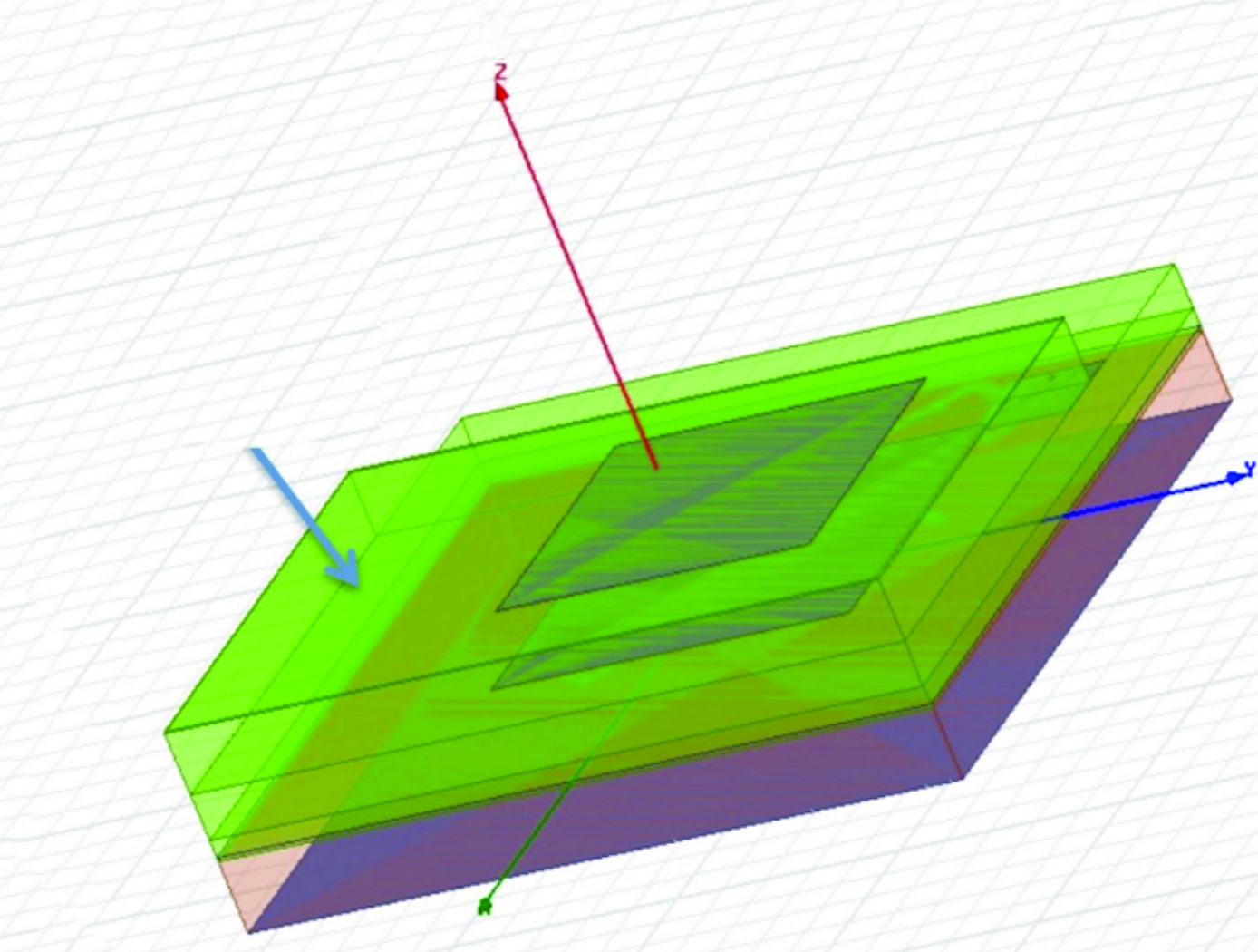
High Performance, All-Metal X-Band Patch Antenna
The patch antenna consists of two radiating metal patch elements, a metal feed circuit, choke rings, several alignment spacers, a SMA connector, and a mounting lid giving the antenna a total diameter of 54 mm; small enough to fit in a coffee cup. The signal is carried between the lower patch and the circuit via a coaxial transmission structure, in which the probes are the inner conductor and the antenna structure is the outer conductor. The patch antenna is constructed entirely of metal, offering rugged physical durability while delivering superior performance. This advanced material not only enables the antenna to handle higher power loads (exceeding 10 watts) but also ensures exceptional stability under demanding conditions—outperforming standard patch antennas made with traditional dielectric materials. It is also not susceptible to the manufacturing variability incurred from using dielectrics. Ideally, this metallic design also allows for reentry and reuse across missions.
The patch antenna is designed with integrated choke rings to effectively mitigate multipath signal interference, delivering an impressive front-to-back ratio of over 35 dB. Its integrated polarizer circuit enhances signal clarity and boosts overall efficiency, ensuring reliable communication in challenging environments. With support for both right- and left-handed circular polarization, the antenna achieves a co-polarization peak gain of 9 dBi and an axial ratio of less than 3 dB within a wide 50-degree orientation range. These advanced features provide superior signal performance and consistent clarity across diverse applications.
Although designed for space and planetary exploration applications, the antenna may also be valuable for terrestrial use cases with rugged conditions. The X-band patch antenna is at technology readiness level (TRL) 5 (component and/or breadboard validation in relevant environment) and is available for patent licensing.
Manufacturing

Automated Fabric Circuit and Antenna Fabrication
Modern production of e-textiles utilizes an embroidery technique called “e-broidery” that directly stitches circuit patterns with conductive thread onto textiles. This automated manufacturing process combines steps of e-broidery and milling to expand the application of e-textiles to high-current and high-speed uses. Manufacturing begins with two layouts of the desired conductive pattern. After assembling the layers of conductive and nonconductive materials, e-broidery is performed with the second layout and nonconductive thread to secure the layers together and designate the pattern for the conductive material. The secured assembly is transferred to an automated milling or laser cutting machine, which cuts the desired conductive pattern and releases the unneeded portions of the conductive material. The resulting e-textiles are tightly woven together, providing higher surface conductivity and impedance control. Initial comparison tests assessing the performance of fabric-based spiral antennas developed with this method, compared to conventional antennas, indicated no loss in performance across multiple metrics, including voltage standing wave ratio (VSWR), radiation pattern, and axial ratio performance.
The Method and Apparatus for Fabric Circuits and Antennas is a technology readiness level (TRL) 6 (system/subsystem prototype demonstration in a relevant environment). The innovation is now available for your company to license. Please note that NASA does not manufacture products itself for commercial sale.
Communications

Conformal, Lightweight, Aerogel-Based Antenna
This CLAS-ACT is a lightweight, active phased array conformal antenna comprised of a thin multilayer microwave printed circuit board built on a flexible aerogel substrate using new methods of bonding. The aerogel substrate enables the antenna to be fitted onto curved surface. NASA's prototype operates at 11-15 GHz (Ku-band), but the design could be scaled to operate in the Ka-band (26 to 40 GHz).
The antenna element design incorporates a dual stacked patch for wide bandwidth to operate on both the uplink and downlink frequencies with a common aperture. These elements are supported by a flexible variant of aerogel that allows the material to be thick in comparison to the wavelength of the signal with little to no additional weight. The conformal antenna offers advantages of better aerodynamics for the airframe, and potentially offers more physical area to either broadcast further distances or to broadcast at a higher data rate. The intended application for this antenna is for UAVs that need more than line of sight communications for command and control but cannot accommodate a large satellite dish. Examples may be UAVs intended for coastal monitoring, power line monitoring, emergency response, and border security where remote flying over large areas may be expected. Smaller UAVs may benefit greatly from the conformal antenna. Another possible application is a UAV mobile platform for Ku-band satellite communication.
With the expectation that 5G will utilize microwave frequencies this technology may be of interest to other markets outside of satellite communications. For example, the automotive industry could benefit from a light weight conformal phased array for embedded radar. Also, the CLAS-ACT could be used for vehicle communications or even vehicle to vehicle communications.
Instrumentation

Dual-Polarized, Wideband, Lightweight P-band Antenna Element and Array
The P-band antenna array is built from rows and columns of antenna elements for the purpose of allowing beam steering up to the maximum desirable angle without incurring grating lobes in the radiation patterns. For flexible mission planning, a large array can be built from several of the small, panel-like elements. The elements are deployable from a folded or stacked stowed configuration during launch, arranged side by side during operation. Each antenna element is itself a fully functional small antenna array. The number of panels can be chosen as dictated by the mission objectives and budget.
Three geometries were designed and tested. Geometry 1 features non-planar metal structures with minimal dielectric support, where the back cavity is closed. Geometry 2 features non-planar metal structures with minimal composite sheet dielectric support, but with an open cavity. Both geometries avoid large flat sheets, which are vulnerable to bending, thereby increasing the mechanical stiffness of the structure while using only thin sheet metal and maintaining an exceptionally low mass-to-size ratio. Geometry 3 features planar metal structures, with sandwich composite dielectric support and an open cavity. While it does not benefit from the mechanical stiffness utilized in non-planar designs, the planar sandwich structure increase robustness and reduces the cost of fabrication. All element geometries have wideband capabilities and are dual polarized.
Although designed for space and planetary exploration, the P-band antenna is also valuable for various terrestrial use cases. The P-band antenna array is at technology readiness level (TRL) 5 (component and/or breadboard validation in relevant environment) and is available for patent licensing.
Sensors

Hyper-Distributed RFID Antenna (HYDRA) System
Components of the HYDRA system include an RFID reader (aka an RFID transceiver or interrogator), RF cables, antennas, and one or more Intelligent Multiplexer Modules (IMMs). The IMM is the core building block of the HYDRA system. In one of its basic embodiments, the IMM comprises an RF directional coupler, RF switch, RFID chip, micro-controller, and power generation and management hardware. In this basic implementation, a single RF port from the RFID reader is attached to the IMM and transfers power thereto. Internally within the IMM, the RF directional coupler diverts a small amount of RF power to rectification and power management circuitry for conversion to DC power that drives the RFID chip, microcontroller, and RF switch. The RFID chip enables communication with the RFID reader and allows the reader to administer changes to the microcontroller‘s embedded software. The microcontroller controls the RF switch, which passes power along to one or more output channels. Connections to the output channels can include antennas, additional IMMs, or other sensors.
The HYDRA system may include numerous alternate embodiments to enhance and customize the basic functionality. In one embodiment, the microcontroller is replaced with a simple timer. In another embodiment, the switch has multiple output ports to connect to a distributed chain of HYDRA system or local antennas. Also, the entirety of RF power exiting a HYDRA module can be rectified and used to power a local sensor node, which could be implemented via WiFi or Bluetooth Low Energy (BLE). Features of the HYDRA system include the ability to cover both open regions and enclosures, the ability to switch RF power to an unused load for assisting in the resolution of tag antenna ambiguities, and the ability to accept plug-and-play add-ons such that the reader’s software can use the system without requiring any embedded modifications.
The HYDRA system is technology readiness level (TRL) 7 (system prototype demonstrated in an operational environment) and is now available for patent licensing. Please note that NASA does not manufacture products itself for commercial sale.
Communications
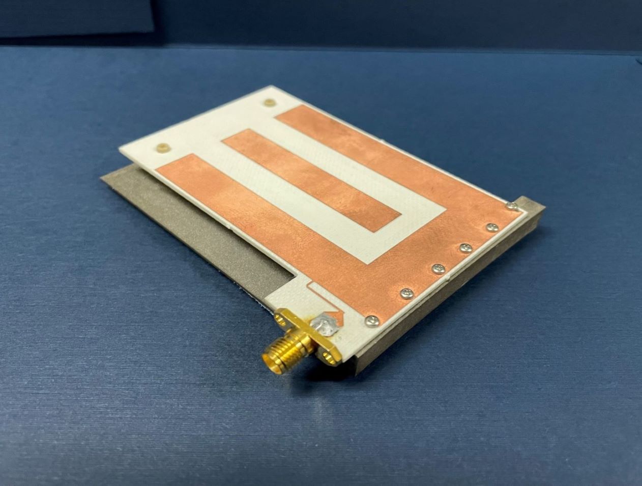
Multi-and Wide-Band Single-Feed Patch Antenna
NASA's patch antenna technology exhibits higher operational bandwidth (on the order of 20%) than typical patch antennas (less than 10%) and can operate across integer-multiple frequency bands (e.g. S/X, C/X, S/C). Testing of the antenna design has demonstrated > 6dB of gain on both S and X bands (boresight), with an axial ratio of < 6dB and voltage standing wave ratio (VSWR) < 3:1 throughout the entire near-Earth network (NEN) operating bands (22.4GHz and 88.4GHz) with hemispherical coverage. The patch size is on the order of 10 x 10 cm and with associated electronics, is about 1 cm in height.
communications

Vortex Radiometer for Wireless Communications
The Vortex Radiometer (VR) creates concentric, annular antenna beam patterns that measure sky-noise temperature. Annular antenna patterns are created by imparting orbital angular momentum into the electric field received by the antenna using spiral phase plates placed in front of the antenna aperture, generating multiple radiometer channels. Data points are then collected by plotting the measured noise temperature of each radiometer channel as a function of time. Noise temperature increases as a noise source (e.g., weather-related noise, signal interference, etc.) traverses the antenna beam patterns. An algorithm is then used to correlate noise temperature peaks in adjacent beams and to determine when a fade will occur, how long the fade will last, and how intense the fade will be. With this information, effective and efficient strategies can be implemented using cognitive communication and antenna systems to autonomously select the optimum fade-mitigation technique and parameter (e.g., increasing the transmission power, adjusting the modulation and/or coding scheme, etc.).
NASA's VR system has been prototyped, including the radiometer device and the algorithm for characterizing noise sources based on VR data. Simulations have shown that a VR system can instruct an existing cognitive antenna to switch between Ka- and X-Band communications in order to avert interference from small diameter noise sources.
Any high-performance communication systems operating in RF or optical frequencies may benefit from NASA's VR capabilities.
Sensors
Low Mass Antenna Boosts RFID Device Performance
NASA’s HYDRA system enables a new approach in routing the RFID signal, greatly increasing extensibility and the number of antennas that can be served by a single reader. However, increasing the number of antennas in any environment is often undesirable unless the antenna size is inconspicuous. Basing this RFID dual mode antenna on a quarter-wavelength structure allows it to be smaller than an antenna designed for half-wavelength structure, reducing overall mass.
NASA’s RFID dual mode antenna is enabled by utilizing two different types of resonance modes – a “slot” mode and a microstrip “patch” mode. An innovative feed architecture allows for coupling from the RFID reader into both modes, with the impedance of each mode approximately equal at respective resonant frequencies. The antenna is designed such that each mode resonates at a different portion of the operating bandwidth, and further with each mode radiating an orthogonal polarization to the other. Frequency-hopping RFID protocols, used in conjunction with this antenna, result in the polarization diversity required for readers to reliably communicate with arbitrarily oriented RFID tags.
Numerous commercial applications exist for this RFID dual mode antenna. Examples may include usage in a multiple antenna architecture that is connected to a single reader in an open-air region, in a small, enclosed region such as a cabinet drawer, or through a combination of open and closed regions.
This RFID dual mode antenna has a technology readiness level (TRL) 7 (system prototype demonstrated in an operational environment) and is now available for patent licensing. Please note that NASA does not manufacture products itself for commercial sale.

