Search
optics
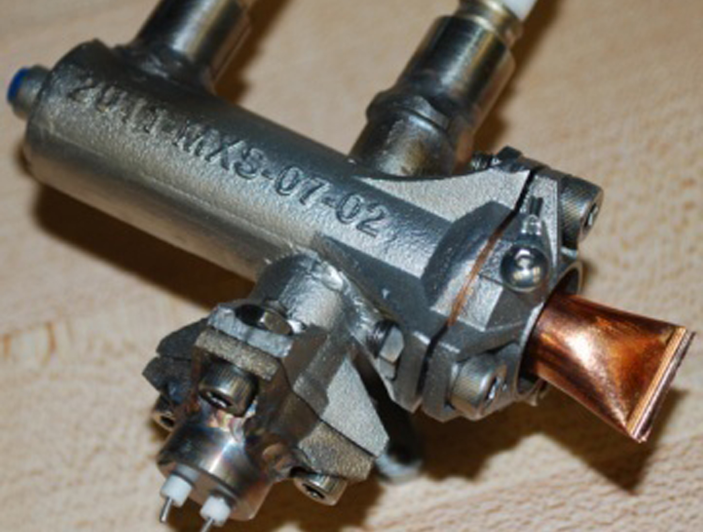
Miniaturized High-Speed Modulated X-Ray Source (MXS)
The MXS produces electrons by shining UV light from an LED onto a photocathode material such as magnesium. The electrons are then accelerated across several kV and into a chosen target material; deceleration produces X-rays characteristic of the target. The MXS uses an electron multiplier for high X-ray production efficiency.
The MXS is more compact, rugged, and power-efficient than standard X-ray sources. It can be manufactured using commercially available components and 3D printed housing, resulting in a low cost to manufacture. Unlike traditional X-ray sources, the MXS does not require a filament or vacuum and cooling systems. Most importantly, enabling rapid and arbitrary modulation allows using X-rays in the time domain, a new dimension to X-ray applications.
aerospace
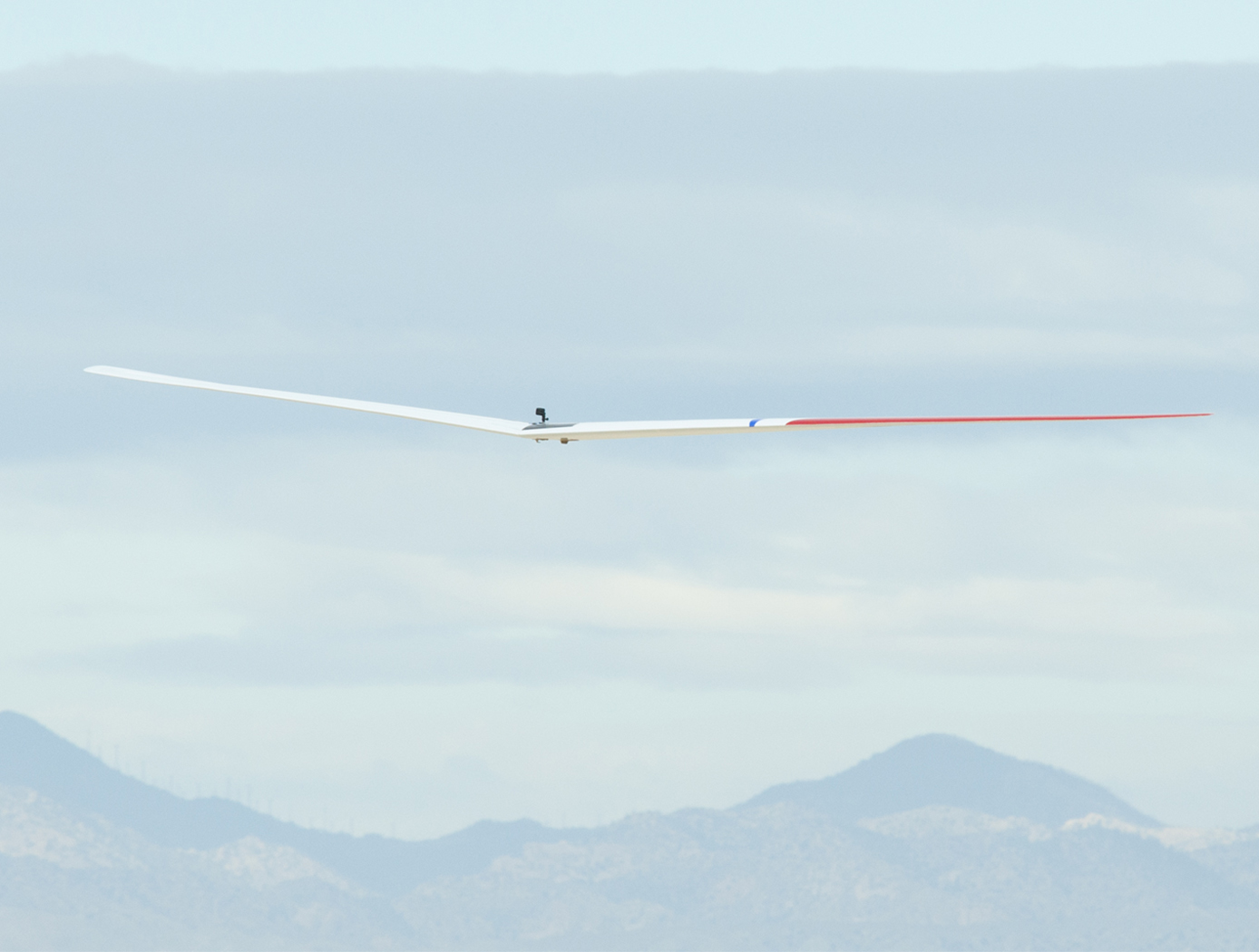
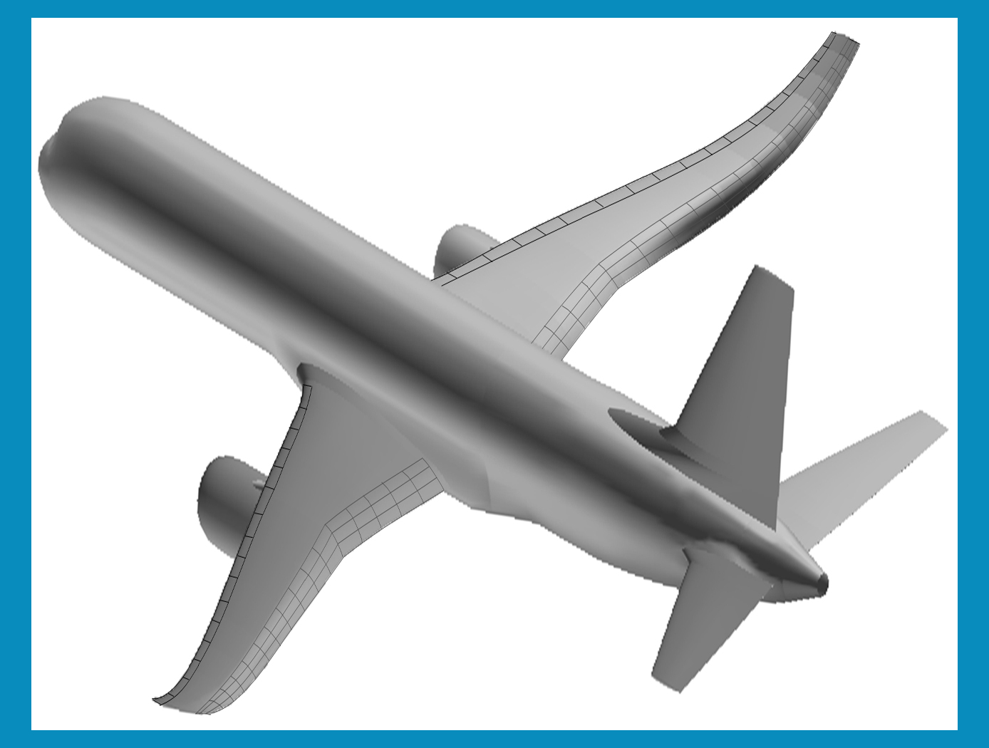
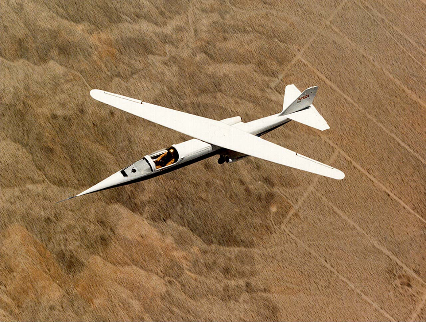
New Wing Design Exponentially Increases Total Aircraft Efficiency
Adverse yaw, present in current aircraft design, is the adverse horizontal movement around a vertical axis of an aircraft; the yaw opposes the direction of a turn. As an aircraft turns, differential drag of the left and right wings while banking contributes to aircraft yaw. Proverse yaw—yawing in the same direction as a turn—would optimize aircraft performance. Initial results from flight experiments at Armstrong demonstrated that this wing design unequivocally established proverse yaw. This wing design further reduces drag due to lift at the same time.
<strong>How It Works</strong>
The Armstrong team (supported by a large contingent of NASA Aeronautics Academy interns) built upon the 1933 research of the German engineer Ludwig Prandtl to design and validate a scale model of a non-elliptical loaded wing that reduces drag and increases efficiency.
The key to the innovation is reducing the drag of the wing through use of an alternative bell-shaped spanload, as opposed to the conventional elliptical spanload. To achieve the bell spanload, designers used a sharply tapered wing, with 12 percent less wing area than the comparable elliptical spanload wing. The new wing has 22 percent more span and 11 percent less area, resulting in an immediate 12 percent drag reduction.
Furthermore, using twist to achieve the bell spanload produces induced thrust at the wing tips, and this forward thrust increases when lift is increased at the wingtips for roll control. The result is that the aircraft rolls and yaws in the same direction as a turn, eliminating the need for a vertical tail. When combined with a blended-wing body, this approach maximizes aerodynamic performance, minimizes weight, and optimizes flight control.
<strong>Why It Is Better</strong>
Conventional aircraft make use of elliptical loaded wings to minimize drag. However, achieving aircraft stability and control in conventional elliptical wings produces a strong adverse yaw component in roll control (i.e., the aircraft will yaw the opposite direction with application of roll control). Therefore, a vertical tail or some other method of direct yaw control is required, such as split elevons for use as drag rudders. The use of elliptical wings also results in a suboptimal amount of structure to carry the integrated wing bending moment.
Adopting the bell-shaped spanload change results in an immediate 12 percent drag reduction. In addition, optimization of the overall aircraft configuration is projected to achieve additional significant overall performance increases.
information technology and software
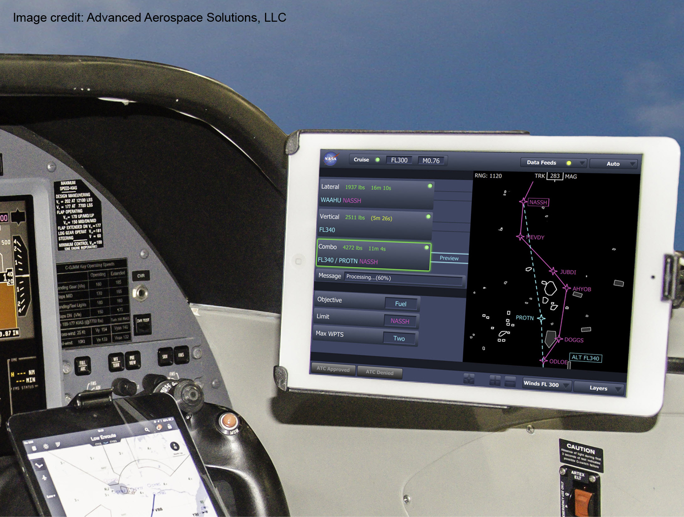
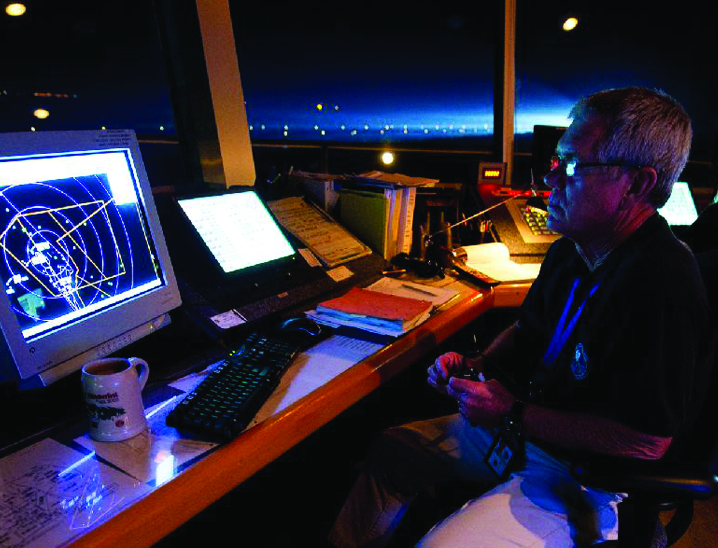
Traffic Aware Strategic Aircrew Requests (TASAR)
The NASA software application developed under the TASAR project is called the Traffic Aware Planner (TAP). TAP automatically monitors for flight optimization opportunities in the form of lateral and/or vertical trajectory changes. Surveillance data of nearby aircraft, using ADS-B IN technology, are processed to evaluate and avoid possible conflicts resulting from requested changes in the trajectory. TAP also leverages real-time connectivity to external information sources, if available, of operational data relating to winds, weather, restricted airspace, etc., to produce the most acceptable and beneficial trajectory-change solutions available at the time. The software application is designed for installation on low-cost Electronic Flight Bags that provide read-only access to avionics data. The user interface is also compatible with the popular iPad. FAA certification and operational approval requirements are expected to be minimal for this non-safety-critical flight-efficiency application, reducing implementation cost and accelerating adoption by the airspace user community.
Awarded "2016 NASA Software of the Year"
aerospace
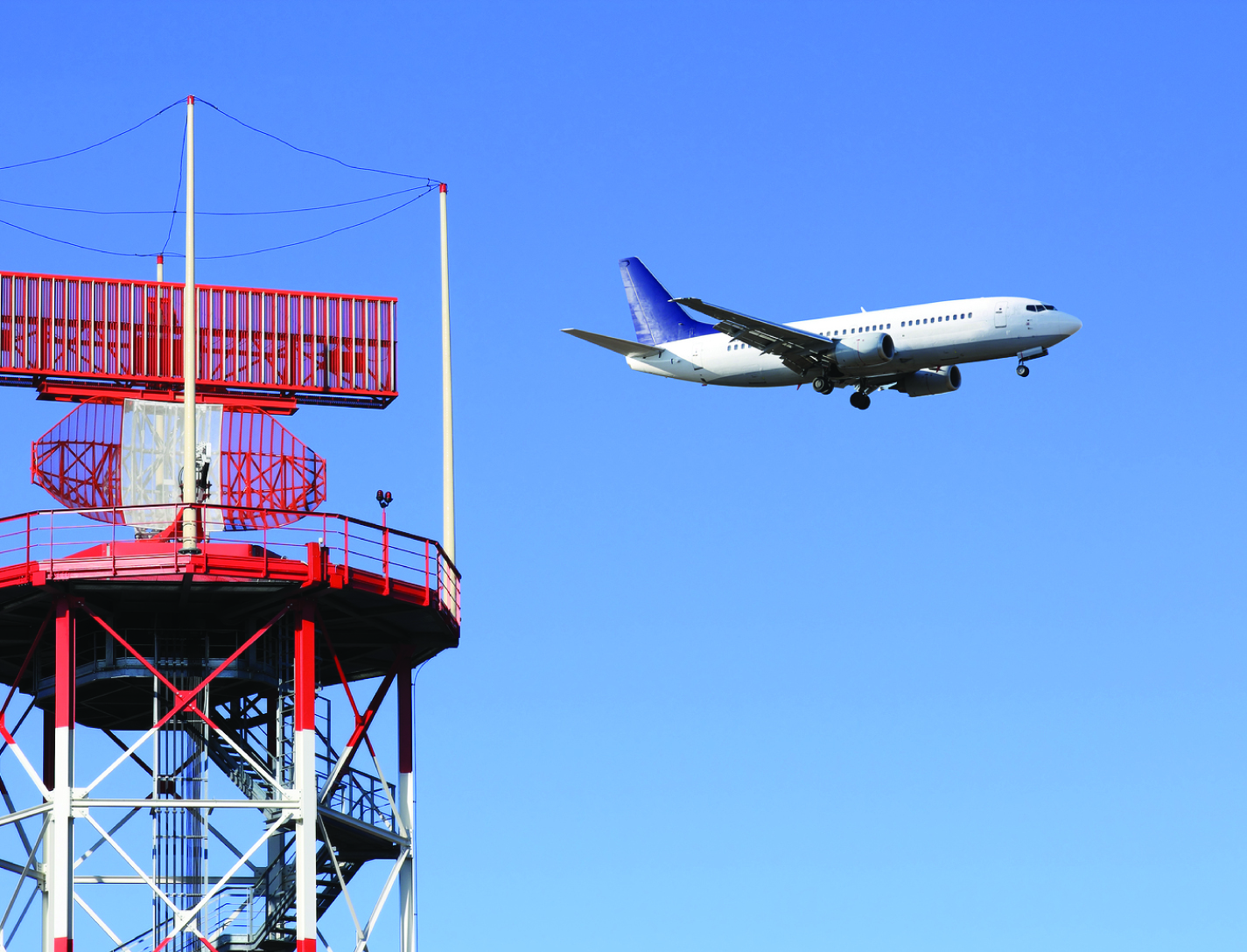
Dynamic Weather Routes Tool
Every 12 seconds, the Dynamic Weather Route (DWR) automation system computes and analyzes trajectories for en-route flights. DWR first identifies flights that could save 5 or more flying minutes (wind-corrected) by flying direct to a downstream return fix on their current flight plan. Eligible return fixes are limited so as not to take flights too far off their current route or interfere with arrival routings near the destination airport. Using the direct route as a reference route, DWR inserts up to two auxiliary waypoints as needed to find a minimum-delay reroute that avoids the weather and returns the flight to its planned route at the downstream fix. If a reroute is found that can save 5 minutes or more relative to the current flight plan, the flight is posted to a list displayed to the airline or FAA user. Auxiliary waypoints are defined using fix-radial-distance format, and a snap to nearby named fix option is available for todays voice-based communications. Users may also adjust the alert criteria, nominally set to 5 minutes, based on their workload and desired potential savings for their flights. A graphical user interface enables visualization of proposed routes on a traffic display and modification, if necessary, using point, click, and drag inputs. If needed, users can adjust the reroute parameters including the downstream return fix, any inserted auxiliary waypoints, and the maneuver start point. Reroute metrics, including flying time savings (or delay) relative to the current flight plan, proximity to current and forecast weather, downstream sector congestion, traffic conflicts, and conflicts with special use airspace are all updated dynamically as the user modifies a proposed route.
aerospace
Green aviation - improved aerodynamic efficiency and less fuel burn
Currently, as fuel is burned, wing loading is reduced, thereby causing the wing shape to bend and twist. This wing-shape change causes the wings to be less aerodynamically efficient. This problem can be further exacerbated by modern high-aspect flexible wing design. Aircraft designers typically address the fuel efficiency goal by reducing aircraft weights, improving propulsion efficiency, and/or improving the aerodynamics of aircraft wings passively. In so doing, the potential drag penalty due to changes in the wing shapes still exists at off-design conditions. The unique or novel features of the new concepts are:
1. Variable camber flap provides the same lift capability for lower drag as compared to a conventional flap. The variable camber trailing edge flap (or leading edge slat) comprises multiple chord-wise segments (three or more) to form a cambered flap surface, and multiple span-wise segments to form a continuous trailing edge (or leading edge) curve with no gaps which could be prescribed by a mathematical function or the equivalent with boundary conditions enforced at the end points to minimize tip vortices
2. Continuous trailing edge flap (or leading edge slat) provides a continuously curved trailing edge (or leading edge) with no gaps to minimize vortices that can lead to an increase in drag.
3. The active wing-shaping control method utilizes the novel flap (or slat) concept described herein to change a wing shape to improve aerodynamic efficiency by optimizing span-wise aerodynamics.
4. An aeroelastic wing shaping method for analyzing wing deflection shape under aerodynamic loading is used in a wing-control algorithm to compute a desired command for the flap-actuation system to drive the present flap (or slat) system to the correct position for wing shaping.
aerospace
FACET: Future Air Traffic Management Concepts Evaluation Tool
Actual air traffic data and weather information are utilized to evaluate an aircrafts flight-plan route and predict its trajectories for the climb, cruise, and descent phases. The dynamics for heading (the direction the aircraft nose is pointing) and airspeed are also modeled by the FACET software, while performance parameters, such as climb/descent rates and speeds and cruise speeds, can also be obtained from data tables. The resulting trajectories and traffic flow data are presented in a 3-D graphical user interface. The FACET software is modular and is written in the Java and C programming languages. Notable FACET applications include reroute conformance monitoring algorithms that have been implemented in one of the Federal Aviation Administrations nationally deployed, real-time operational systems.
aerospace
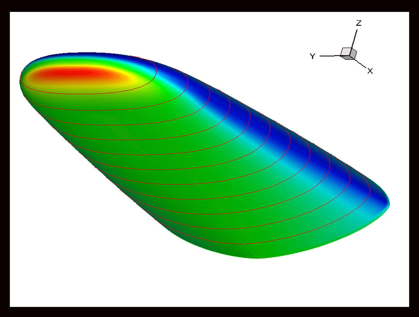
Co-Optimization of Blunt Body Shapes for Moving Vehicles
Vehicles designed for purposes of exploration of the planets and other atmospheric bodies in the Solar System favor the use of mid-Lift/Drag blunt body geometries. Such shapes can be designed so as to yield favorable hypersonic aerothermodynamic properties for low heating and hypersonic aerodynamic properties for maneuverability and stability. The entry trajectory selected influences entry peak heating and integrated heating loads which in turn influences the design of the thermal protection system. A nominal is used to compare each shape considered. The vehicle will be subject to both launch and entry loading along with structural integrity constraints that may further influence shape design. Further, such vehicles must be sized so as to fit on existing or realizable launch vehicles, often within existing launch payload shroud constraints.
optics
Spatial Standard Observer (SSO)
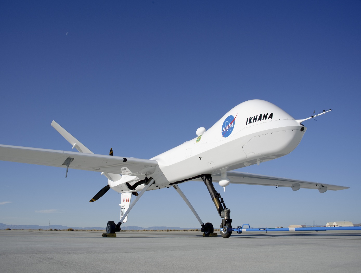
The Spatial Standard Observer (SSO) provides a tool that allows measurement of the visibility of an element, or visual discriminability of two elements. The device may be used whenever it is necessary to measure or specify visibility or visual intensity. The SSO is based on a model of human vision, and has been calibrated by an extensive set of human test data. The SSO operates on a digital image or a pair of digital images. It computes a numerical measure of the perceptual strength of the single image, or of the visible difference between the two images. The visibility measurements are provided in units of Just Noticeable Differences (JND), a standard measure of perceptual intensity.
A target that is just visible has a measure of 1 JND. The SSO will be useful in a wide variety of applications, most notably in the inspection of displays during the manufacturing process. It is also useful in for evaluating vision from unpiloted aerial vehicles (UAV) predicting visibility of UAVs from other aircraft, from the control tower of aircraft on runways, measuring visibility of damage to aircraft and to the shuttle orbiter, evaluation of legibility of text, icons or symbols in a graphical user interface, specification of camera and display resolution, inspection of displays during the manufacturing process, estimation of the quality of compressed digital video, and predicting outcomes of corrective laser eye surgery.
Aerospace
Variable Geometry Aircraft Wing Supported By Struts and/or Trusses
This innovation utilizes a strut/truss-braced oblique variable-sweep wing mounted on a constant cross-section geometry fuselage. The combination of the strut/truss-bracing with the oblique wing greatly reduces the structural and weight penalties previously associated with unbraced oblique wing configurations while maintaining the oblique wings improved aerodynamic performance. Strut/truss bracing helps to further reduce the wing weight, and can be used to automatically align wing-mounted engines with the oncoming flow. The synergistic combination of these design elements provides the aircraft with a wide and efficient cruise speed range when the wing is at intermediate sweep positions, and superior low speed performance when the wing is unswept. The wing could remain aligned during taxiing, reducing the chance of collisions with other taxiing aircraft. This wide speed envelope provides future air traffic systems with additional flexibility when scheduling efficient arrivals and departures. The improved climb performance of the straight wing reduces the neighborhood noise footprint of the aircraft as it departs the airport. Efficient aircraft designs are increasingly desired in order to support the continued growth of the air transportation industry. Continued expansion of this vital mode of transportation is threatened by ever-increasing challenges in emissions, noise, and fuel efficiency.
sensors

Method and Device for Biometric Verification and Identification
The advantage of using cardiac biometrics over existing methods is that heart signatures are more difficult to forge compared to other biometric devices. Iris scanners can be fooled by contact lenses and sunglasses, and a segment of the population does not have readable fingerprints due to age or working conditions. Previous electrocardiographic signals employed a single template and compared that template with new test templates by means of cross-correlation or linear-discriminant analysis.The benefit of this technology over competing cardiac biometric methods is that it is more reliable with a significant reduction in error rates. The benefit of this technology is that it creates a probabilistic model of the electrocardiographic features of a person instead of a single signal template of the average heartbeat. The probabilistic model described as Gaussian mixture model allows various modes of the feature distribution, in contrast to a template model that only characterizes a mean waveform. Another advantage is that the model uses both physiological and anatomical characterization of the heart, unlike other methods that mainly use only physiological characterization of the heart. By combining features from different leads, the heart of the person is better characterized in terms of anatomical orientation because each lead represents a different projection of the electrical vector of the heart. Thus, employing multiple electrocardiographic leads provides a better performance in subject verification or identification.

