Search
Sensors

Capacitive Impedance Water Ice Sensor (CIWIS)
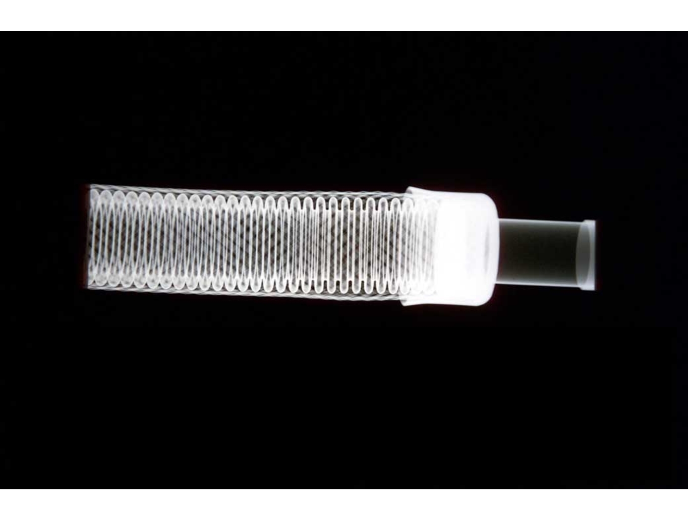
The CIWIS is configured to detect ice, water, and other material accretion on an aircraft's surface using a capacitive sensor comprised of metal traces on a printed circuit board (PCB) with a dielectric surface covering. The traces are on the bottom side of the PCB for protection from the elements experienced on the top side. It drives the sensor with a sinusoidal signal and monitors the sensed sinusoidal signal from the sensor. By electronically measuring the RMS voltage of both the drive and sensed signal as well as the phase shift introduced by the sensor, the CIWIS can determine the impedance of the sensor and any material deposition. When a material is present on the surface, this introduces another capacitor in parallel with the air and PCB, with that material being another dielectric.
Water and ice exhibit frequency-dependent permittivity that introduces a phase shift unlike that of a typical capacitor. CIWIS leverages these differences, distinguishing materials by the unique RMS levels and phase shifts they produce in the sensor. For ice, this effect occurs at approximately 10 kHz.
While NASA originally developed the CIWIS to detect ice on aircraft, it may also be useful to sense the presence of water and other contaminants in pharmaceutical production; condensation in heating, ventilation, and air conditioning (HVAC) systems; and ice accumulation on cryogenic equipment. This technology is available for patent licensing, and is rated at a Technology Readiness Level or TRL of 5 , meaning it has been developed and validated in an industrially relevant environment and is ready for a prototype demonstration.
information technology and software

Meta Monitoring System (MMS)
Meta Monitoring System (MMS) was developed as an add-on to NASA Ames patented Inductive Monitoring System (IMS), which estimates deviation from normal system operations. MMS helps to interpret deviation scores and determine whether anomalous behavior is transient or systemic. MMS has two phases: a model-building training phase, and a monitoring phase. MMS not only uses deviation scores from nominal data for training but can also make limited use of results from anomalous data. The invention builds two models: one of nominal deviation scores and one of anomalous deviation scores, each consisting of a probability distribution of deviation scores. After the models are built, incoming deviation scores from IMS (or a different monitoring system that produces deviation scores) are passed to the learned model, and probabilities of producing the observed deviation scores are calculated for both models. In this fashion, users of MMS can interpret deviation scores from the monitoring system more effectively, reducing false positives and negatives in anomaly detection.
Note: Patent license only; no developed software available for licensing
Manufacturing
X-Ray Crack Detectability
NASAs software technology uses an Image Quality Indicator (IQI)-based model that can predict whether cracks of a certain size can be detected, as well as a model that can provide appropriate conditions to optimize x-ray crack detection setup. Because this modeling software can predict minimum crack sizes that can be detected by a particular X-ray radiography testing setup, users can test various setups until the desired crack detection capabilities are achieved (predicted) by the modeling system.
These flaw size parameter models use a set of measured inputs, including thickness sensitivity, detector modulation transfer function, detector signal response function, and other setup geometry parameters, to predict the minimum crack sizes detectable by the testing setup and X-ray angle limits for detecting such flaws.
Current X-ray methods provide adequate control for detection of volumetric flaws but do not provide a high probability of detection (POD), and crack detection sensitivity cannot be verified for reliable detection. This results in reduced confidence in terms of crack detection. Given that these cracks, if undetected, can cause catastrophic failure in various systems (e.g., pressure vessels, etc.), verifying that X-ray radiography systems used for NDE can detect such cracks is of the utmost importance in many applications.
Manufacturing

Optimization of X-Ray CT Measurement Accuracy for Metal AM Components
This NASA innovation is a method for quantifying and improving accuracy of X-Ray CT-based metal AM part inspection by comparing X-Ray CT data with a high-fidelity 2D surface imaging technique such as surface profilometry. Using surface profilometry that has a NIST-traceable calibration, the technique guarantees a specific level of high fidelity, allowing surface profilometry data to serve as a ground truth reference with which to judge X-Ray CT accuracy and detectability.
To deploy the method, both 3D X-Ray CT data and 2D high-fidelity surface images are acquired on the same metal AM part. 3D X-Ray CT data is then segmented and reoriented to extract a 2D X-Ray CT surface image. Measurements of features (e.g., surface-breaking porosity) are then made in both datasets, followed by a comparison of various metrics. This comparison serves two purposes: (a) quantifying the accuracy of the X-Ray CT inspection performed, and (b) providing an objective function which can be minimized to optimize X-Ray CT inspection. The objective function allows engineers to tune X-Ray CT parameters to minimize the function. These optimized parameters can then be implemented to achieve higher accuracy and defect detection reliability in X-Ray CT imaging. Once an X-Ray CT process is optimized for a specific metal AM component, analysis and certification can be accelerated.
This technology helps develop X-Ray CT-based metal AM part inspection processes with high accuracy and reliable detectability. Industries for which metal AM parts are desirable and safety, reliability, and fatigue life is of concern (e.g., aerospace, commercial space, automotive, medical) could benefit from the invention. Companies including X-Ray CT inspection system manufacturers using optical sensors and software, NDE data analysis software providers, and end-users in the industries may be interested in licensing this NASA invention.
aerospace

Advanced Fire Detection for Aircraft Cargo Holds
Traditional cargo fire detection systems rely on fixed thresholds, such as a specific temperature, to trigger alarms. However, these static approaches are prone to false positives and may miss slow-developing fires. This patented system introduces a novel method that evaluates sensor data dynamically, based on both spatial location and temporal evolution. Temperature sensors distributed throughout the cargo compartment generate continuous data streams which are analyzed over defined time windows. The system compares sensor values across locations and over time, identifying anomalies that indicate real fire events rather than harmless fluctuations. Configurable parameters allow operators to adapt detection sensitivity to different operational conditions, cargo types, and environmental variables. This method supports early detection of fires in Class C cargo compartments, including those inaccessible during flight. It is designed to integrate with aircraft health monitoring and fire suppression systems, and it can be deployed in both new aircraft designs and as a retrofit to existing platforms equipped with sensor arrays.
Aerospace
3D Lidar for Autonomous Landing Site Selection
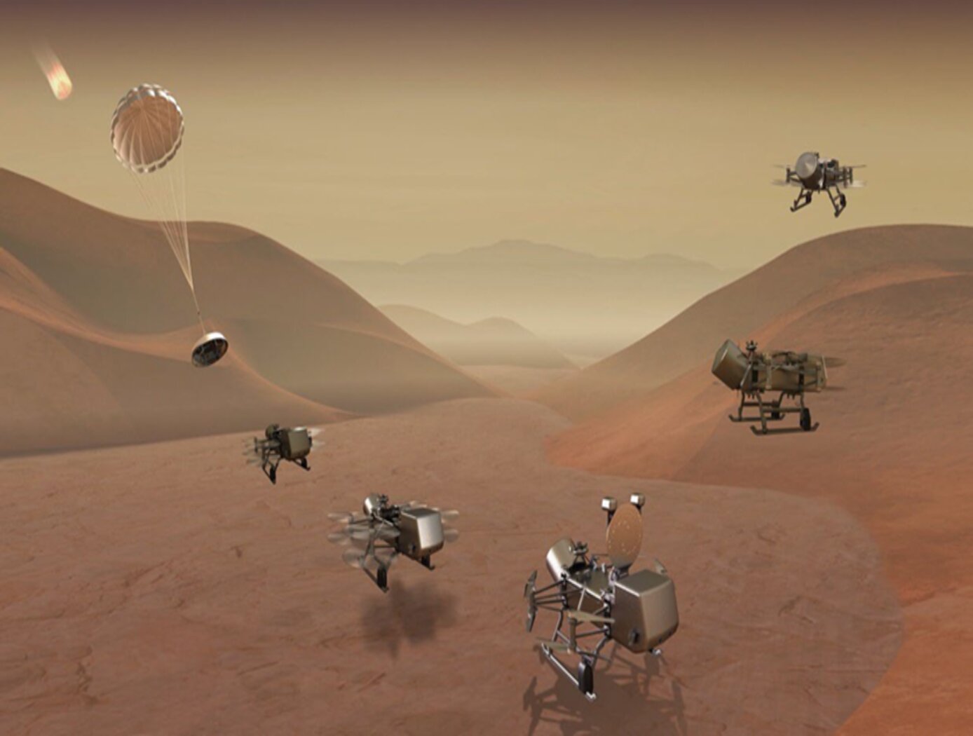
Aerial planetary exploration spacecraft require lightweight, compact, and low power sensing systems to enable successful landing operations. The Ocellus 3D lidar meets those criteria as well as being able to withstand harsh planetary environments. Further, the new tool is based on space-qualified components and lidar technology previously developed at NASA Goddard (i.e., the Kodiak 3D lidar) as shown in the figure below.
The Ocellus 3D lidar quickly scans a near infrared laser across a planetary surface, receives that signal, and translates it into a 3D point cloud. Using a laser source, fast scanning MEMS (micro-electromechanical system)-based mirrors, and NASA-developed processing electronics, the 3D point clouds are created and converted into elevations and images onboard the craft. At ~2 km altitudes, Ocellus acts as an altimeter and at altitudes below 200 m the tool produces images and terrain maps. The produced high resolution (centimeter-scale) elevations are used by the spacecraft to assess safe landing sites.
The Ocellus 3D lidar is applicable to planetary and lunar exploration by unmanned or crewed aerial vehicles and may be adapted for assisting in-space servicing, assembly, and manufacturing operations. Beyond exploratory space missions, the new compact 3D lidar may be used for aerial navigation in the defense or commercial space sectors. The Ocellus 3D lidar is available for patent licensing.
Instrumentation

Reconfigurable Local Oscillator for Coherent Optical Detection
The innovation expands the range of signals that coherent optical receivers can detect. Unlike traditional systems with fixed LOs, this approach allows real-time adjustments to an LO’s properties, such as frequency, phase, polarization, amplitude, spatial mode, or timing, to better match incoming signals. These adjustments improve measurement accuracy and signal recovery in various scenarios, such as shifting heterodyne frequencies into the receiver’s bandwidth or adapting to different signal polarizations. The innovation lies in the ability to switch an LO's configurations on the fly using technologies like fiber-optic or integrated photonic switches, as well as other methods like optical modulation or tunable delay lines. This dynamic capability allows coherent receivers to switch seamlessly between range-Doppler and Doppler-only modes. As a result, a single system can track both nearby, slow-moving targets and distant, high-velocity objects (up to 20+ km/s) while operating with a compact, low-speed receiver (<1 GHz). This versatility significantly enhances the performance and adaptability of advanced optical sensing and communication systems.
While initially developed for NASA’s Navigation Doppler LiDAR project, this invention can support advanced signal detection applications across several industries, including optical communications, aerospace, structural health monitoring, and autonomous vehicles. By enabling real-time reconfiguration, the invention offers improved signal recovery, enhanced sensitivity, and broader system adaptability for challenging detection environments. The technology has gone through prototype development and is currently at TRL 3 (proof-of-concept), and the reconfigured LO is available for patent licensing.
sensors
In Situ Performance Monitoring of Piezoelectric Sensors and Accelerometers
On occasion, anomalies may appear in the highly dynamic test data obtained during rocket engine tests, which are investigated and corrective action may be mandated before subsequent testing. Also, it is often unclear if anomalies in recorded signals are due to differences between the Low and High Speed Data Acquisitions Systems, difference between the transducers, a failed transducer, or if everything is working correctly and the system were actually accurately recording real events. Commercial test equipment suitable for testing piezoelectric sensors is expensive and requires that the sensor be removed from the test article for evaluation. With the monitoring system developed, degraded sensor performance can be quickly and economically identified.
This system can evaluate installed piezoelectric sensors, without requiring physical contact with or removing them from their mounted locations. Tests are conducted through cabling. Since it is not necessary to remove the device, data that reflect the devices specific physical configuration (such as as-mounted resonant frequency) are retained, and devices that are physically inaccessible can still be tested. The testing system is not limited to identifying degraded performance in the sensors piezoelectric elements; it can detect changes within the entire sensor, and sensor housing.
The system can be made portable, in a battery powered sealed box, for testing in the field. Since physical contact with the sensor is not necessary, therefore, monitoring can be done as far away as 250 feet, or longer if certain provisions are made.
Optics
Fingerprinting for Rapid Battery Inspection
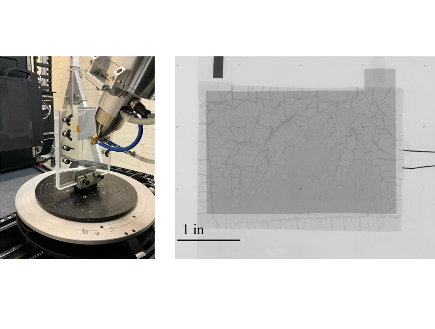
The technology utilizes photopolymer droplets (invisible to the digital radiograph) with embedded radiopaque fragments to create randomized fingerprints on battery samples. The droplets are deposited using a jig (see figure on right) that precisely positions samples. Then, at different points during battery R&D testing or use, digital radiography imaging with micron-level resolution can be performed.
The high-resolution imaging required to detect dendrite formation requires images to be collected in multiple “tiles” as shown below. The randomized fingerprints uniquely identify relative positioning of these tiles, allowing rapid assembly of composite high-resolution images from multiple tiles.
This same composite creation process can be used for images taken at a series of points in time during testing, and background subtraction can be applied to efficiently compare how the battery is changing over successive charge/discharge cycles to identify dendrite formation. This inspection technique is proven effective for thin-film pouch cell prototypes at NASA, and it works well at the lowest available x-ray energy level (limiting impact on the samples). The Fingerprinting for Rapid Battery Inspection technology is available for patent licensing.
Optics

Portable Integrated Fourier Ptychographic Microscope
NASA’s integrated, portable FPM device combines advanced optical microscopy with AI in a compact form factor. At its core, the system uses a Raspberry Pi camera module equipped with an 8-megapixel sensor and a 3-mm focal-length lens, achieving approximately 1.5× magnification. Illumination is provided by a Unicorn HAT HD LED array positioned 65mm below the sample stage, creating a synthetic numerical aperture of 0.55. All these components are controlled by an NVIDIA Jetson Nano board, which serves as the system's embedded AI computing platform. NASA’s portable FPM device can be integrated with a microfluidic system for sub-micron imaging of liquid samples.
In addition to its portability, what sets NASA’s integrated FPM device apart is its integration of deep learning capabilities. The invention has two modes – normal mode and deep learning mode. In its normal mode, the system captures data and performs intensity and 3D phase analysis using traditional FPM methods. The deep learning mode enhances this base functionality by employing neural networks for image reconstruction and system optimization. The AI system automatically detects when samples are out of focus and can either mechanically or digitally adjust to the correct focal plane. To achieve near real-time monitoring, deep learning models significantly reduce data acquisition time by selectively using only a portion of the LED array and provide fast reconstruction capabilities leveraging training on specific sample types.
While originally designed for imaging biosignature motility in liquid samples for spaceflight applications, this NASA innovation can image many different types of samples, and is not limited to biological specimens. The ability to operate this system in the field further broadens use-cases.

