Search
Robotics Automation and Control

Visual Inspection Posable Invertebrate Robot (VIPIR)
Initially developed as a close quarters inspection tool capable of accessing hard to reach, tight, or visibly restricted, areas of satellites, the VIPIR system can be used to remotely inspect inaccessible locations such as behind a sheet of thermal blanketing material, into a satellites plumbing, or perhaps even deep inside the otherwise unreachable crevasses of a spacecraft bus. The VIPIR system incorporates a number of subassemblies for incredible operational freedom and capabilities for imaging and dissemination of componentry.
VIPIR’s Video Borescope Assembly (VBA) is a flexible snake-camera capable of multidirectional articulations, making steering and control simple and intuitive for an operator. The VBA also includes at least one imaging sensor and lighting to see in dark, confined spaces. Real-time, high-resolution visual information can be fed back to an operator for live analysis. A reel system extends and retracts the VBA with the use of a spool, and includes position indicators for deployment tracking. The Tendon Management System (TMS), not unlike human tendons, utilizes pulleys and tensioners to articulate the VBA in the confined spaces. A seal system ensures the VBA is free of contamination.
VIPIR underwent space-based testing on the ISS during the Robotic Refueling Phase 2 (RRM-2) mission designed to showcase and test several NASA advanced robotic satellite servicing technologies. During this mission, VIPIR demonstrated state-of-the-art near and midrange inspection capabilities. NASA’s VIPIR system is available for licensing to industry, and may be desirable to companies focused on satellite servicing, on-orbit assembly, and other applications requiring detailed inspection of assets in space.
Robotics Automation and Control

Robotic System for Infra-structure Reconnaissance
The robotic system is comprised of six main components: the orb that performs the reconnaissance, an orb injector housing that attaches to a piping network, a tether and reel subsystem that attaches to the back of the injector housing, a fluid injection subsystem that attaches toward the front of the injector housing, an external power and data subsystem, and associated control and monitoring software.
Usage of the system begins with an operator attaching the injector housing, with the orb stowed inside, to a flanged gate valve belonging to the piping network of concern. Requisite power, data, and fluid subsystems are attached, and the system is energized for usage. The orb is released via the tether and reel, and a controlled fluid force is imparted on the orb to help guide it along its mission. The tether supplies power and guidance to the orb, and relays real-time data back to the operator.
The orb’s interior features a modular plug-and-play architecture which may comprise COTS instrumentation for reconnaissance or investiga-tion, LIDAR, and inertial measuring and motion sensors. This instru-mentation could be used in combination with other sub-systems such as lighting, and core and sample retrieving mechanisms. These com-ponents are supported by other onboard devices such as a CPU, power source and controller, and data transmission encoders and multiplexers.
The Robotic System for Infrastructure Reconnaissance is at TRL 8 (actual system completed and "flight qualified" through test and demonstration), and is now available for licensing. Please note that NASA does not manufacture products itself for commercial sale.
Sensors

Advanced Thermal Inspection with Pulsed Light Emitting Diodes (PLED) Technology
NASA’s PLED thermal inspection system consists of an array of high- powered LED chips configured to deliver controlled pulses of visible light. The system includes 8 LED chip arrays, mounted on an aluminum heat sink and housed in a hood configuration. The inspection hood is specially designed with filters to prevent internal reflections. The LEDs are powered by regulated power supplies and controlled via a computer interface that synchronizes heat pulses with an infrared camera. An acrylic filter is placed over the LEDs to block residual infrared radiation, ensuring that only visible light reaches the target surface. The system’s infrared camera, operating in the mid-wave infrared (MWIR) range does not detect the visible light and captures the transient thermal response of the material, allowing for precise defect detection. By eliminating the need for high-intensity broadband infrared sources, the PLED system provides a cleaner and more accurate thermal response, particularly for unpainted metals and additively manufactured (AM) components.
Performance validation of the PLED system has demonstrated significant advantages over traditional flash thermography. In tests on aluminum samples with material loss and AM Ti-6Al-4V metal specimens, the PLED system successfully detected defects with superior contrast and no heat source reflections. Principal Component Analysis (PCA) applied to PLED inspection data revealed clearer defect indications compared to flash-based methods, which introduced unwanted artifacts due to transient reflections. Additionally, the PLED system enabled quantitative thermal diffusivity measurements, offering a new approach to single-sided material characterization.
NASA's PLED thermal inspection technology is available for patent licensing. Potential applications include corrosion detection in aerospace components, quality control of AM metal parts, structural health monitoring of industrial materials, and more.
Sensors

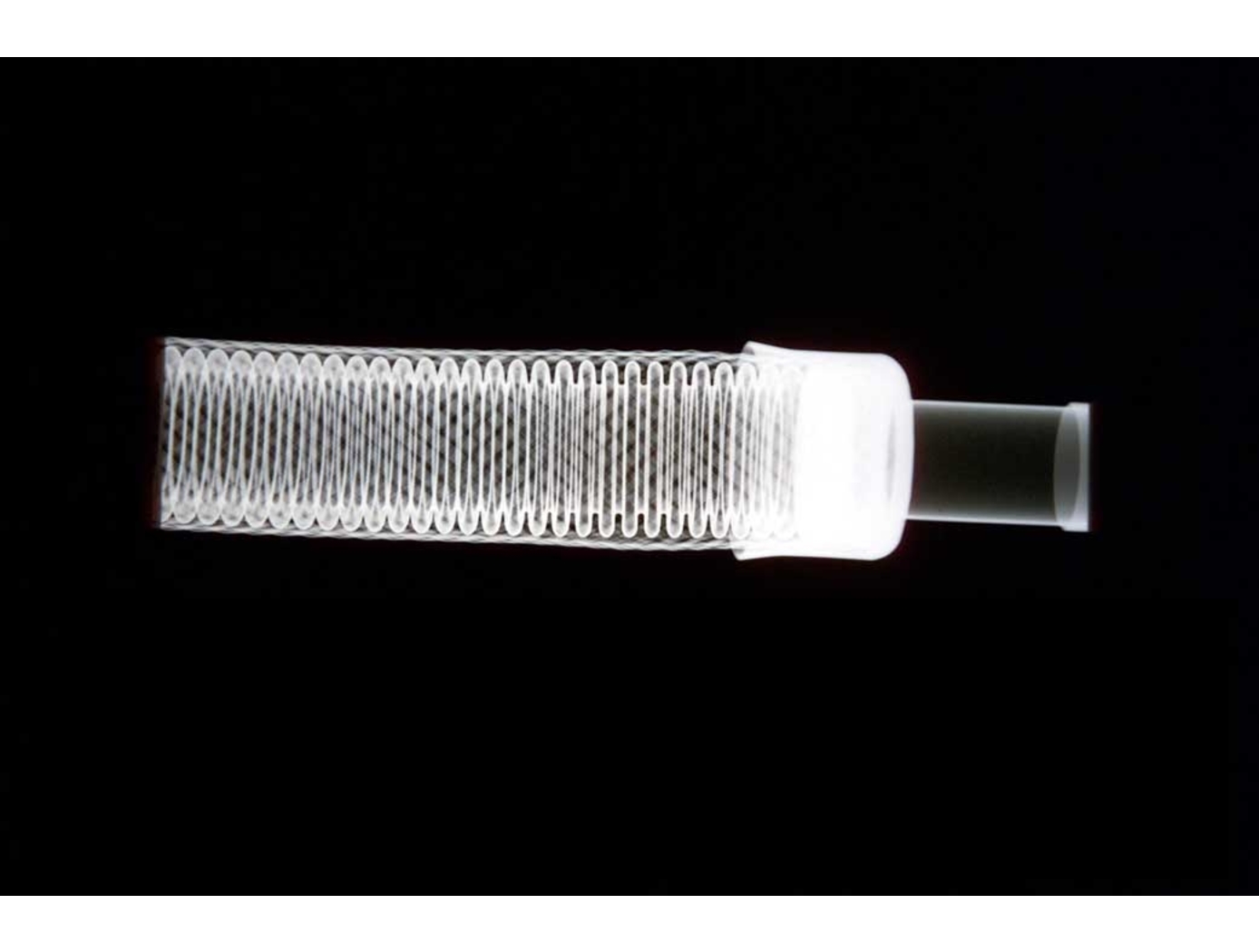
A Generalized Ultrasonic Inspection Method for Batteries
The generalized ultrasonic inspection method harnesses piezoelectric transducers and ultrasonic resonance spectroscopy to detect sub-500-micron defects in batteries. By analyzing the resonance behavior of high-frequency sound waves and employing novel data processing techniques, subtle structural changes in batteries can be identified. Two hardware setups were developed: one employing direct transducer contact and another utilizing ultrasonic measurements through a captured water column. Both configurations incorporate a scanning technique that captures spatial degradation data – rather than a single point measurement – enabling structural insights even in layers too thin for time-domain c-scan resolution.
Processing of the data includes converting the measurements and reference time domain signals to the frequency domain, then normalizing the measurement signal in the frequency domain to determine the frequency dependent reflection coefficient. As a result, resonance behavior between the test specimen and apparatus can be isolated. This resonance-based approach is ideal for delicate materials unsuitable for high-powered laser excitation or full immersion testing, and the associated data-analysis allows the battery defects to be detected more efficiently.
This NASA invention offers significant potential for highly sensitive, nondestructive enhancements of battery safety and quality control in industries such as automotive, aerospace, additive manufacturing, and composites.
Optics
Fingerprinting for Rapid Battery Inspection
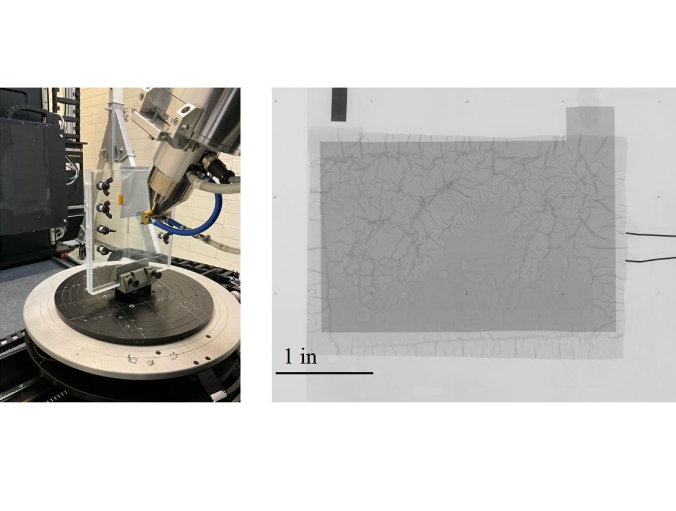
The technology utilizes photopolymer droplets (invisible to the digital radiograph) with embedded radiopaque fragments to create randomized fingerprints on battery samples. The droplets are deposited using a jig (see figure on right) that precisely positions samples. Then, at different points during battery R&D testing or use, digital radiography imaging with micron-level resolution can be performed.
The high-resolution imaging required to detect dendrite formation requires images to be collected in multiple “tiles” as shown below. The randomized fingerprints uniquely identify relative positioning of these tiles, allowing rapid assembly of composite high-resolution images from multiple tiles.
This same composite creation process can be used for images taken at a series of points in time during testing, and background subtraction can be applied to efficiently compare how the battery is changing over successive charge/discharge cycles to identify dendrite formation. This inspection technique is proven effective for thin-film pouch cell prototypes at NASA, and it works well at the lowest available x-ray energy level (limiting impact on the samples). The Fingerprinting for Rapid Battery Inspection technology is available for patent licensing.
Robotics Automation and Control

Anonymous Feature Processing for Enhanced Navigation
This concept presents a new statistical likelihood function and Bayesian analysis update for non-standard measurement types that rely on associations between observed and cataloged features. These measurement types inherently contain non-standard errors that standard techniques, such as the Kalman filter, make no effort to model, and this mismodeling can lead to filter instability and degraded performance.
Vision-based navigation methods utilizing the Kalman filter involve a preprocessing step to identify features within an image by referencing a known catalog. However, errors in this pre-processing can cause navigation failures. AFP offers a new approach, processing points generated by features themselves without requiring identification. Points such as range or bearing are directly processed by AFP.
Operating on finite set statistics principles, AFP treats data as sets rather than individual features. This enables simultaneous tracking of multiple targets without feature labeling. Unlike the sequential processing of the Kalman filter, AFP processes updates in parallel, independently scoring each output based on rigorous mathematical functions. This parallel processing ensures robust navigation updates in dynamic environments, and without requiring an identification algorithm upstream of the filter.
Computational simulations conducted at Johnson Space Center demonstrate that AFP's performance matches or exceeds that of the ideal Kalman filter, even under non-ideal conditions. Anonymous Feature Processing for Enhanced Navigation is at a technology readiness level (TRL) 4 (component and/or breadboard validation in laboratory environment) and is now available for patent licensing. Please note that NASA does not manufacture products itself for commercial sale.
Information Technology and Software

Computer Vision Lends Precision to Robotic Grappling
The goal of this computer vision software is to take the guesswork out of grapple operations aboard the ISS by providing a robotic arm operator with real-time pose estimation of the grapple fixtures relative to the robotic arm’s end effectors. To solve this Perspective-n-Point challenge, the software uses computer vision algorithms to determine alignment solutions between the position of the camera eyepoint with the position of the end effector – as the borescope camera sensors are typically located several centimeters from their respective end effector grasping mechanisms.
The software includes a machine learning component that uses a trained Region-based Convolutional Neural Network (R-CNN) to provide the capability to analyze a live camera feed to determine ISS fixture targets a robotic arm operator can interact with on orbit. This feature is intended to increase the grappling operational range of ISS’s main robotic arm from a previous maximum of 0.5 meters for certain target types, to greater than 1.5 meters, while significantly reducing computation times for grasping operations.
Industrial automation and robotics applications that rely on computer vision solutions may find value in this software’s capabilities. A wide range of emerging terrestrial robotic applications, outside of controlled environments, may also find value in the dynamic object recognition and state determination capabilities of this technology as successfully demonstrated by NASA on-orbit.
This computer vision software is at a technology readiness level (TRL) 6, (system/sub-system model or prototype demonstration in an operational environment.), and the software is now available to license. Please note that NASA does not manufacture products itself for commercial sale.
Manufacturing
X-Ray Crack Detectability
NASAs software technology uses an Image Quality Indicator (IQI)-based model that can predict whether cracks of a certain size can be detected, as well as a model that can provide appropriate conditions to optimize x-ray crack detection setup. Because this modeling software can predict minimum crack sizes that can be detected by a particular X-ray radiography testing setup, users can test various setups until the desired crack detection capabilities are achieved (predicted) by the modeling system.
These flaw size parameter models use a set of measured inputs, including thickness sensitivity, detector modulation transfer function, detector signal response function, and other setup geometry parameters, to predict the minimum crack sizes detectable by the testing setup and X-ray angle limits for detecting such flaws.
Current X-ray methods provide adequate control for detection of volumetric flaws but do not provide a high probability of detection (POD), and crack detection sensitivity cannot be verified for reliable detection. This results in reduced confidence in terms of crack detection. Given that these cracks, if undetected, can cause catastrophic failure in various systems (e.g., pressure vessels, etc.), verifying that X-ray radiography systems used for NDE can detect such cracks is of the utmost importance in many applications.

