Search
Instrumentation

Dual-Polarized, Wideband, Lightweight P-band Antenna Element and Array
The P-band antenna array is built from rows and columns of antenna elements for the purpose of allowing beam steering up to the maximum desirable angle without incurring grating lobes in the radiation patterns. For flexible mission planning, a large array can be built from several of the small, panel-like elements. The elements are deployable from a folded or stacked stowed configuration during launch, arranged side by side during operation. Each antenna element is itself a fully functional small antenna array. The number of panels can be chosen as dictated by the mission objectives and budget.
Three geometries were designed and tested. Geometry 1 features non-planar metal structures with minimal dielectric support, where the back cavity is closed. Geometry 2 features non-planar metal structures with minimal composite sheet dielectric support, but with an open cavity. Both geometries avoid large flat sheets, which are vulnerable to bending, thereby increasing the mechanical stiffness of the structure while using only thin sheet metal and maintaining an exceptionally low mass-to-size ratio. Geometry 3 features planar metal structures, with sandwich composite dielectric support and an open cavity. While it does not benefit from the mechanical stiffness utilized in non-planar designs, the planar sandwich structure increase robustness and reduces the cost of fabrication. All element geometries have wideband capabilities and are dual polarized.
Although designed for space and planetary exploration, the P-band antenna is also valuable for various terrestrial use cases. The P-band antenna array is at technology readiness level (TRL) 5 (component and/or breadboard validation in relevant environment) and is available for patent licensing.
Robotics Automation and Control
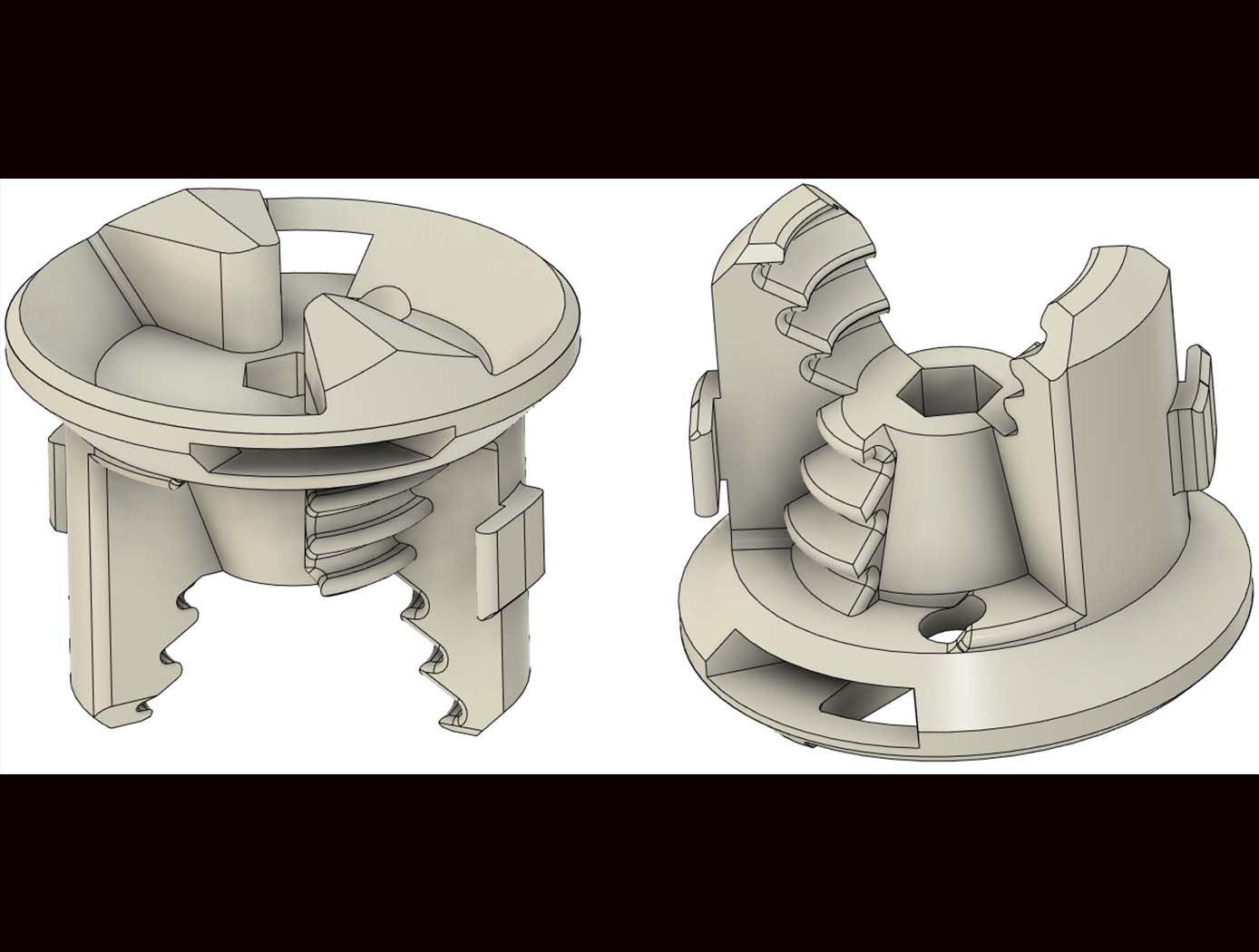
Reversible Androgynous Mechanical Fastener
The androgynous fastener is lightweight and facilitates assembly through simple actuation with large driver-positioning tolerance requirements. This fastener provides a high-strength, reversible mechanical connection and may be used in high strength-to-weight ratio structural systems, such as lattice structure systems. The androgynous fastener resists tensile and shear forces upon loading of the lattice structure system thereby ensuring that the struts of the lattice structure system govern the mechanical behavior of the system. The androgynous fastener eliminates building-block orientation requirements and allows assembly in all orthogonal build directions. This androgynous fastener may be captive in building-block structural elements thereby minimizing the logistical complexity of transporting additional fasteners. Integration of a plurality of the androgynous fasteners into a high performance, robotically managed, structural system reduces launch energy requirements, enables higher mission adaptivity and decreases system life-cycle costs. The androgynous fastener is beneficial in any application where robotic end effectors are used to join structural components (or other parts) together. It may be particularly desirable for applications requiring frequent movement of hardware to an assembly site to replace joint connections.
Robotics Automation and Control

Robotic System for Infra-structure Reconnaissance
The robotic system is comprised of six main components: the orb that performs the reconnaissance, an orb injector housing that attaches to a piping network, a tether and reel subsystem that attaches to the back of the injector housing, a fluid injection subsystem that attaches toward the front of the injector housing, an external power and data subsystem, and associated control and monitoring software.
Usage of the system begins with an operator attaching the injector housing, with the orb stowed inside, to a flanged gate valve belonging to the piping network of concern. Requisite power, data, and fluid subsystems are attached, and the system is energized for usage. The orb is released via the tether and reel, and a controlled fluid force is imparted on the orb to help guide it along its mission. The tether supplies power and guidance to the orb, and relays real-time data back to the operator.
The orb’s interior features a modular plug-and-play architecture which may comprise COTS instrumentation for reconnaissance or investiga-tion, LIDAR, and inertial measuring and motion sensors. This instru-mentation could be used in combination with other sub-systems such as lighting, and core and sample retrieving mechanisms. These com-ponents are supported by other onboard devices such as a CPU, power source and controller, and data transmission encoders and multiplexers.
The Robotic System for Infrastructure Reconnaissance is at TRL 8 (actual system completed and "flight qualified" through test and demonstration), and is now available for licensing. Please note that NASA does not manufacture products itself for commercial sale.
Manufacturing
Modular Artificial-Gravity Orbital Refinery Spacecraft
Modular Artificial-Gravity Orbital Refinery Spacecraft is a solution for refining in-situ materials collected in space, such as from asteroids and Mars moons, as well as recycling spacecraft debris, while orbiting in micro-gravity conditions. The spacecraft is coupled with refining modules for refining and recycling different types of materials. It generates artificial gravity for operation in low-gravity environments. The spacecraft is comprised of rotating rings, each generating artificial gravity and angular momentum. When the rotating rings are combined on the spacecraft platform, however, they have a net near-zero angular momentum such that the spacecraft can change its attitude with minimal propellant or rotate at the rate of the object the spacecraft platform is attached to. The spacecraft platform can self-balance to accommodate different sized modules and modules with moving loads. The refined and recycled materials can be used to create products in-situ as well as products too large to launch from Earth, such as construction of orbiting space habitats, large spacecraft, solar-power stations, and observatories.
Optics

Multi-Edge Slant Target for Non-Localized MTF Measurement
NASA’s Multi-Edge Slant Target is a precision-manufactured 1-inch diameter chrome-on-quartz calibration plate featuring a sophisticated geometric pattern optimized for comprehensive MTF analysis. The repeated slant edges allow for MTF to be directly sampled across the sensor in discrete locations, as opposed to solely in the center along a single edge of the image. Once the target plate is imaged, the image files can be used to calculate MTF measurements using standard methods as outlined in ISO 12233. The MTF data can then be visualized as a heatmap, which illustrates image quality of the imaging system as a function of discretely localized optical aberrations or spatial non-uniformities in the system’s electro-optical assembly.
Fabricated using advanced laser lithography techniques with sub-micron precision, NASA’s target provides exceptional contrast ratios meeting ISO 12233 standards. The chrome coating creates sharp, high-contrast edges on a clear quartz substrate, enabling backlit operation with blackbody or integrating sphere sources across broad spectral ranges. The target's unique geometric design includes positioning markers for precise alignment and multiple sampling regions that enable enhanced MTF measurement accuracy.
NASA’s Multi-Edge MTF Slant Target can be used in any application requiring characterization of 2D imaging systems from UV-VIS to MWIR. Firms that develop multi-spectral, hyper-spectral, thermal, and visible light imaging systems may benefit from the full-field spatial performance characterization it enables. Slant targets manufacturers may be interested in adding this capability to their product lines. The invention has been fabricated and validated (it is frequently used by NASA’s SCIFLI team), and is available for patent licensing.
Aerospace

Elastic Shape Morphing of Ultra-Light Structures by Programmable Assembly
The technology uses a base set of the substructure, interface, and skin building blocks to design an aerostructure that maximize the aerodynamic loading of the aero structure while maintaining the appropriate safety factor. The main substructure building blocks used are octahedral unit cells, which, when connected at their nodes, produce a cuboctahedral lattice structure. The interface building block set connects the vertices of the substructure building blocks to the skin components and the root and tip plates. The skin is a collection of flat and curved plates that are designed to overlap one-another and to transfer aerodynamic pressure loads directly to the substructure through the interface parts. Panels are not interconnected and thus do not behave as a structural stressed skin. Neighboring panels overlap by 10.2mm to ensure a continuous surface for airflow while still allowing panels to slide past one another during aeroelastic shape change. The structure was developed with adherence to the following guidelines: (i) All second voxel type groupings are limited to linear string shapes; (ii) No second voxel type grouping string can be longer than three blocks long; (iii) Second voxel type grouping strings can not be placed within two unit spaces of each other; (iv) Second voxel type grouping strings placed spanwise will reduce bending and torsional stiffness; (v) Second voxel type grouping strings placed chordwise decreases airfoil shape stability; (vii) Second voxel type grouping strings reduce the total length of building block extrusion.
Environment

Modular Container System Preserves Sample Integrity
The Astromaterials Acquisition and Curation Office (AACO) at NASA Johnson Space Center currently curates 500 milligrams of the regolith sample from the Asteroid Ryugu that was collected by the Japan Aerospace and Exploration Agency’s Hayabusa II spacecraft and returned to Earth in 2021. In September 2023, NASA’s OSIRIS-REx spacecraft returned 70 grams of regolith collected from the surface of Asteroid Bennu. These astromaterial sample collections are stored and handled in gloveboxes and desiccators that are continuously purged with ultrapure nitrogen in order to minimize contamination and alteration of extraterrestrial samples from terrestrial environments.
For collaborative astromaterial sample research conducted outside of the AACO, a need emerged for a sample container system suitable for global transport, capable of maintaining the same low-oxygen envi-ronment as laboratory gloveboxes. Thus, the MCS was developed. MSC’s of different sizes (2, 4, and 8-inch sample container models) have been developed to store contact pads and bulk samples from NASA missions, including the OSIRIS-REx Asteroid Bennu mission.
MCS’s are designed with seal profiles to prevent oxygen from seeping into the sample container. Additionally, the MCS uses a sample container form-factor that optimizes favorable nitrogen to oxygen gas ratios. The final prototypes were tested and verified using optochemical sensors to measure trace oxygen levels within the sealed containers.
The Modular Container System (MCS) could fill a critical gap in the existing high-purity logistics and storage market in its ability to provide a passively maintained, verifiable, multi-year, glovebox-level low-oxygen environment in a portable robust form-factor. Although this technology was originally developed for astromaterial transport and storage, commercial applications may also exist in biopharmaceutical/ bio-banking, microelectronics/ semiconductor, and other industries.

