Search
Aerospace

Real-Time Drag Opti-mization Control Framework
According to the International Air Transport Association statistics, the annual fuel cost for the global airline industry is estimated to be about $140 billion in 2017. Therefore, fuel cost is a major cost driver for the airline industry. Advanced future transport aircraft will likely employ adaptive wing technologies that enable the wings of those aircraft to adaptively reconfigure themselves in optimal shapes for improved aerodynamic efficiency throughout the flight envelope. The need for adaptive wing technologies is driven by the cost of fuel consumption in commercial aviation. NASA Ames has developed a novel way to address aerodynamic inefficiencies experienced during aircraft operation. The real-time drag optimization control method uses an on-board, real-time sensor data gathered from the aircraft conditions and performance during flight (such as engine thrust or wing deflection). The sensor data are inputted into an on-board model estimation and drag optimization system which estimates the aerodynamic model and calculates the optimal settings of the flight control surfaces. As the wings deflect during flight, this technology uses an iterative approach whereby the system continuously updates the optimal solution for the flight control surfaces and iteratively optimizes the wing shape to reduce drag continuously during flight. The new control system for the flight control surfaces can be integrated into an existing flight control system. This new technology can be used on passenger aircraft, cargo aircraft, or high performance supersonic jets to optimize drag, improve aerodynamic efficiency, and increase fuel efficiency during flight. In addition, it does not require a specific aircraft math model which means it does not require customization for different aircraft designs. The system promises both economic and environmental benefits to the aviation industry as less fuel is burned.
Aerospace

Method And System for Enhancing Vehicle Performance and Design Using Parametric Modeling and Gradient-Based Control Integration
The parametric modeling system allows for the integrated design and optimization of aerospace vehicles by unifying physical and control subsystems within a single computational model. The system includes representations of the vehicle’s geometry, structural load, propulsion, energy storage, and GNC systems. The system performs sensitivity analysis on key performance metrics (e.g., fuel consumption, heat load, and mechanical forces) to determine how changes in design parameters affect overall performance. By incorporating real-world conditions, such as wind variations and sensor noise, the system allows for the use of real-time feedback to refine vehicle designs. The optimization process uses a gradient-based algorithm to iteratively adjust parameters so that constraints such as structural integrity, thermal protection, and fuel capacity are met. The system generates a Pareto front representing trade-offs between performance metrics that allow engineers to visualize optimal designs for different mission profiles, which enhances design accuracy while reducing the need for expensive physical testing.
aerospace
Multi-Objective Flight Control Optimization Framework
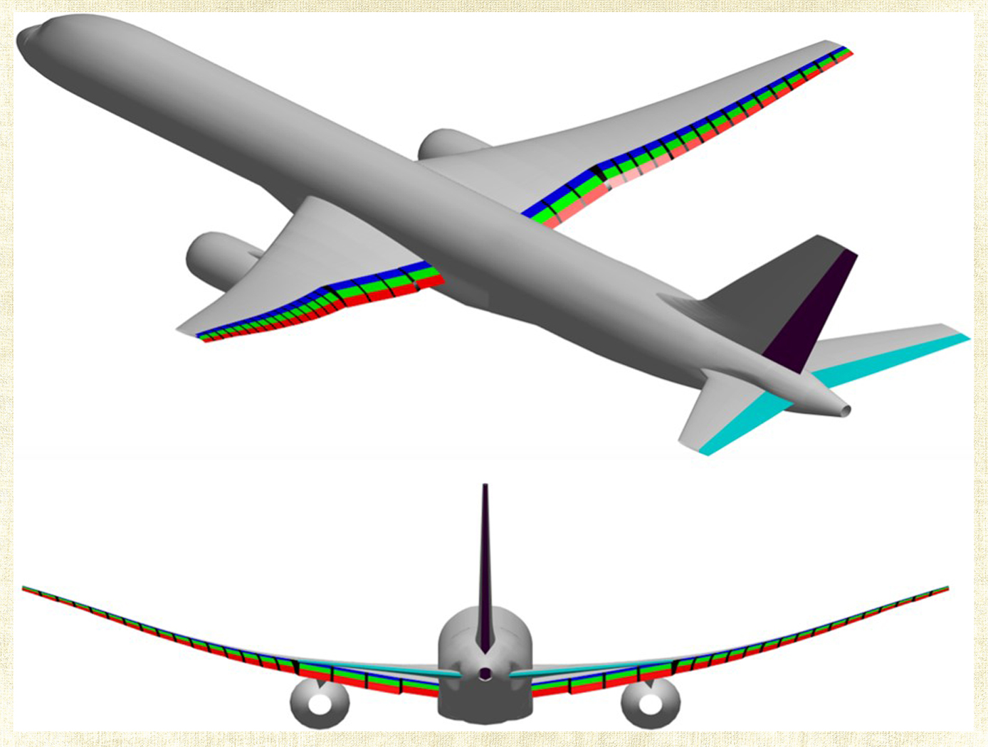
Composite materials are being used in aerospace design because of their high strength-to-weight ratio. On modern airplanes, composite wings offer a greater degree of aerodynamic efficiency due to weight savings, but at the same time introduce more structural flexibility than their aluminum counterparts. Under off-design flight conditions, changes in the wing shape due to structural flexibility cause the wing aerodynamics to be non-optimal. This effect could offset any weight saving benefits realized by the composite wings. Structural flexibility could also cause adverse interactions with flight control and structural vibration which can compromise aircraft stability, pilot handling qualities, and passenger ride quality. NASA Ames Research Center has developed a novel technology that employs a new multi-objective flight control optimization framework to achieve multiple control objectives simultaneously. This technology leverages the availability of distributed flight control surfaces in modern transports. The multi-objective flight control technology comprises the following objectives all acting in a synergistic manner: 1) traditional stability augmentation and pilot command-following flight control, 2) drag minimization, 3) aeroelastic mode suppression, 4) gust load alleviation, and 5) maneuver load alleviation. Each of these objectives can be a major control system design in its own right. Thus, the multi-objective flight control technology can effectively manage the complex interactions of the individual single-objective flight control system design and take into account multiple competing requirements to achieve optimal flight control solutions that have the best compromise for these requirements. In addition, a real- time drag minimization control strategy is included in the guidance loop. This feature utilizes system identification methods to estimate aerodynamic parameters for the on-line optimization. The aerodynamic parameters are also used in the multi-objective flight control for drag minimization and maneuver/ gust load alleviation control.
Manufacturing
X-Ray Crack Detectability
NASAs software technology uses an Image Quality Indicator (IQI)-based model that can predict whether cracks of a certain size can be detected, as well as a model that can provide appropriate conditions to optimize x-ray crack detection setup. Because this modeling software can predict minimum crack sizes that can be detected by a particular X-ray radiography testing setup, users can test various setups until the desired crack detection capabilities are achieved (predicted) by the modeling system.
These flaw size parameter models use a set of measured inputs, including thickness sensitivity, detector modulation transfer function, detector signal response function, and other setup geometry parameters, to predict the minimum crack sizes detectable by the testing setup and X-ray angle limits for detecting such flaws.
Current X-ray methods provide adequate control for detection of volumetric flaws but do not provide a high probability of detection (POD), and crack detection sensitivity cannot be verified for reliable detection. This results in reduced confidence in terms of crack detection. Given that these cracks, if undetected, can cause catastrophic failure in various systems (e.g., pressure vessels, etc.), verifying that X-ray radiography systems used for NDE can detect such cracks is of the utmost importance in many applications.
Aerospace

Optimized Airfoil Design for Aerial Flight Vehicles in Low-Reynolds Flight
This invention, developed under the Rotor Optimization for the Advancement of Mars eXploration (ROAMX) project, provides a method for optimizing airfoil geometries for aerial flight vehicles generally, and can also specifically optimize airfoil geometries for operating in Martian or other low Reynolds number environments. The method introduces a new “ROAMX parameterization” that defines geometric constraints, such as camber node count and the number and order of Bézier curve segments, to generate candidate airfoil shapes. A genetic algorithm evaluates these shapes against multiple objectives and iteratively selects the best-performing designs, converging on a Pareto-optimal front. This enables simultaneous optimization of metrics such as maximizing lift and minimizing drag. Using the ROAMX 1301 parameterization, the method produced an airfoil with lift to drag ratio improvements of up to 42% over the outboard airfoil used on the Mars Helicopter Ingenuity, representing a significant performance gain.

