Search
Robotics Automation and Control

Lunar Surface Navigation System
NASA’s reverse-ephemeris lunar navigation system is a concept for determining position on the lunar surface based on known orbits of satellites. In conventional GPS navigation systems, the GPS satellite transmits ephemeris data to a receiver on earth for determining position at the receiver location. Whereas for the reverse-ephemeris approach the receiver becomes the transmitter, and the satellite instead serves more as a fixed reference position with a known ephemeris. This simplifies the satellite requirements and also mitigates potential navigational disruptions that can otherwise arise in navigation systems that utilize satellite-based communications, for example from interference, jamming, etc.
The design consists of lunar surface S-Band (2,400 – 2,450 MHz) 10 W transceivers ranging with analog translating transponders on a three-satellite constellation in frozen elliptical orbits to provide continuous coverage with service to 300 simultaneous users over 1.8 MHz of bandwidth at the transponder. Digital bases systems are possible too. As compared to GPS-based navigation requiring four or more satellites costing 100’s of millions of dollars, the new NASA concept is based on using only three smallsats.
communications
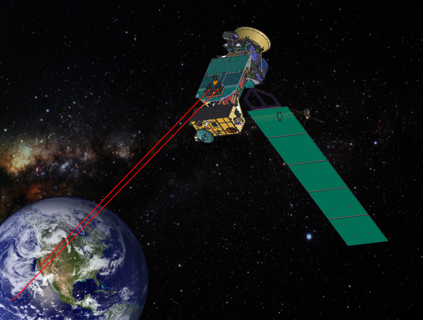
Cascaded Offset Optical Modulator
A unique challenge in the development of a deep space optical SDR transmitter is the optimization of the ER. For a Mars to Earth optical link, an ER of greater than 33 dB may be necessary. A high ER, however, can be difficult to achieve at the low Pulse Position Modulation (PPM) orders and narrow slot widths required for high data rates. The Cascaded Offset Optical Modulator architecture addresses this difficulty by reducing the width of the PPM pulse within the optical modulation subsystem, which relieves the SDR of the high signal quality requirements imposed by the use of an MZM. With the addition of a second MZM and a variable time delay, all of the non-idealities in the electrical signal can be compensated by slightly offsetting the modulation of the laser. The pulse output is only at maximum intensity during the overlap of the two MZMs. The width of the output pulse is effectively reduced by the offset between MZMs. Measurement and analysis of the system displayed, for a 1 nanosecond pulse width, extinction ratios of of 32.5 dB, 39.1 dB, 41.6 dB, 43.3 dB, 45.8 dB, and 48.2 dB for PPM orders of 4, 16, 32, 64, 128, and 256, respectively. This approach is not limited to deep space optical communications, but can be applied to any optical transmission system that requires high fidelity binary pulses without a complex component. The system could be used as a drop-in upgrade to many existing optical transmitters, not only in free space, but also in fiber. The system could also be implemented in different ways. With an increase in ER, the engineer has the choice of using the excess ER for channel capacity, or simplifying other parts of the system. The extra ER could be traded for reduced laser power, elimination of optical amplifiers, or decreased system complexity and efficiency.
Aerospace

Vision-based Approach and Landing System (VALS)
The novel Vision-based Approach and Landing System (VALS) provides Advanced Air Mobility (AAM) aircraft with an Alternative Position, Navigation, and Timing (APNT) solution for approach and landing without relying on GPS. VALS operates on multiple images obtained by the aircraft’s video camera as the aircraft performs its descent. In this system, a feature detection technique such as Hough circles and Harris corner detection is used to detect which portions of the image may have landmark features. These image areas are compared with a stored list of known landmarks to determine which features correspond to the known landmarks. The world coordinates of the best matched image landmarks are inputted into a Coplanar Pose from Orthography and Scaling with Iterations (COPOSIT) module to estimate the camera position relative to the landmark points, which yields an estimate of the position and orientation of the aircraft. The estimated aircraft position and orientation are fed into an extended Kalman filter to further refine the estimation of aircraft position, velocity, and orientation. Thus, the aircraft’s position, velocity, and orientation are determined without the use of GPS data or signals. Future work includes feeding the vision-based navigation data into the aircraft’s flight control system to facilitate aircraft landing.

