Search
Robotics Automation and Control

Visual Inspection Posable Invertebrate Robot (VIPIR)
Initially developed as a close quarters inspection tool capable of accessing hard to reach, tight, or visibly restricted, areas of satellites, the VIPIR system can be used to remotely inspect inaccessible locations such as behind a sheet of thermal blanketing material, into a satellites plumbing, or perhaps even deep inside the otherwise unreachable crevasses of a spacecraft bus. The VIPIR system incorporates a number of subassemblies for incredible operational freedom and capabilities for imaging and dissemination of componentry.
VIPIR’s Video Borescope Assembly (VBA) is a flexible snake-camera capable of multidirectional articulations, making steering and control simple and intuitive for an operator. The VBA also includes at least one imaging sensor and lighting to see in dark, confined spaces. Real-time, high-resolution visual information can be fed back to an operator for live analysis. A reel system extends and retracts the VBA with the use of a spool, and includes position indicators for deployment tracking. The Tendon Management System (TMS), not unlike human tendons, utilizes pulleys and tensioners to articulate the VBA in the confined spaces. A seal system ensures the VBA is free of contamination.
VIPIR underwent space-based testing on the ISS during the Robotic Refueling Phase 2 (RRM-2) mission designed to showcase and test several NASA advanced robotic satellite servicing technologies. During this mission, VIPIR demonstrated state-of-the-art near and midrange inspection capabilities. NASA’s VIPIR system is available for licensing to industry, and may be desirable to companies focused on satellite servicing, on-orbit assembly, and other applications requiring detailed inspection of assets in space.
Aerospace
Spacecraft with Artificial Gravity Modules
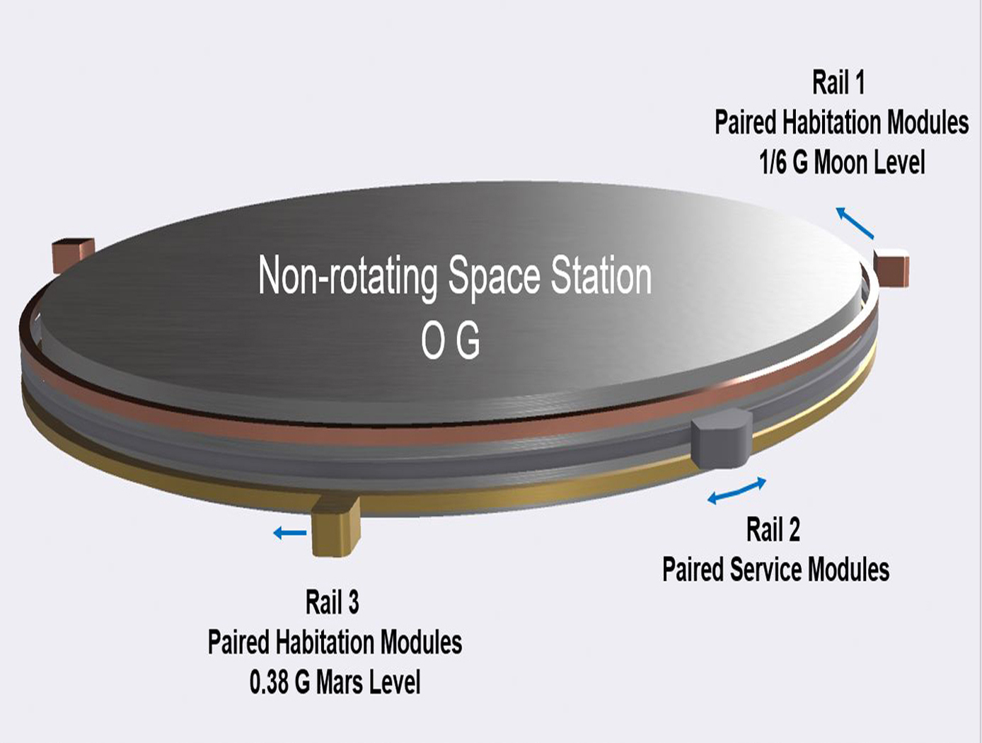
Conventionally, the approaches of creating artificial gravity in space was envisioned as a large rotating space station that creates an inertial force that mimics the effects of a gravitational force. However, generating artificial gravity with large rotating structures poses problems, including (1) the need to mass balance the entire rotating spacecraft in order to eliminate or minimize rotational imbalance causing gyroscopic precession/nutation motions and other oscillations of the rotating spacecraft; (2) the potentially prohibitive cost, time and schedule to build such a large rotating system; (3) the need to mass balance the spacecraft in real-time so as to minimize passenger discomfort and structural stress on the spacecraft; (4) the difficulty in docking other spacecraft to the rotating spacecraft; (5) the absence or minimal presence of non-rotating structure for 0G research and industrial use; and (6) the generation of extraneous Coriolis effect on spacecraft inhabitants. The novel technology can help solve the problems referenced above and other problems by (1) providing a non-rotating space station or structure, and connecting modules that generate artificial gravity by traveling along a circular path around the non-rotating space station; (2) providing modules that are more easily built and balanced; (3) providing a stationary structure that can provide a platform for other components that do not need gravity to function; (4) providing capability to actively interrogate what levels of mass imbalance are acceptable, for use in determining operational constraints; and (5) reducing or eliminating Coriolis effect on occupants in habitation modules. The concepts of the invention are very cost-effective and allow for building a minimal initial system to produce artificial gravity at the first phases of construction, before the full structure is built. An additional benefit is that construction and assembly of new capabilities can be performed without disrupting the ongoing artificial gravity environment of the existing structure.
Propulsion
Anode Manifold Plug for Hall Effect Thrusters
Flow-restricting features in a Hall thruster anode manifold assembly, typically precision manufactured orifices, can contribute to significant flow non-uniformity if tolerances on the features are not properly controlled. Non-uniformity in flow distribution negatively impacts thruster performance. The anode assembly is usually a complex and expensive assembly to manufacture. Removing the flow restricting elements from the anode manifold structure in favor of modular insertable subcomponents (i.e., plugs) enables the use of more reliable and repeatable precision manufacturing techniques. The resulting components can be tested, characterized, and sorted for acceptance before being installed into the larger anode assembly (i.e., quality control can be performed at the subcomponent level). This may lead to increased performance and yield rate of the final assembly.
The flow restrictor plugs can be made in many different ways. The most basic flow restrictor takes the form of a precision hole machined into a cylinder, where the cylinder is then press fit into a hole drilled into the anode base. Alternate embodiments of the flow restrictor include precision machined nozzles, laminar flow elements, or sintered porous metal elements. The flow restrictor can also be made from a different material than the anode base, such as a precision ruby orifice contained in a metal carrier which is installed in a metal anode base. The plugs can be installed in a variety of ways, all of which create hermetic seals. Installation can include a press fit relying on plastic deformation or threading the plug component into the anode base. Welding on the top surface of the anode base can also be done to provide a robust hermetic seal.
propulsion

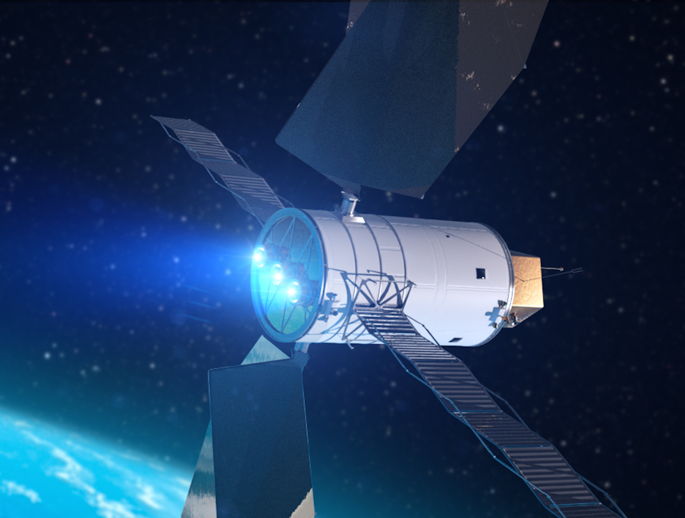
High Propellant Throughput Small Spacecraft Electric Propulsion Thruster
NASAs High Propellant Throughput Small Spacecraft Electric Propulsion thruster offers a propellant throughput capability of greater than 120 kg with a nominal thruster efficiency greater than 50%. The new thruster design combines heritage Hall thruster component design approaches with recent NASA GRC advancements in the areas of advanced magnetic circuit design, robust propellant manifolds, and center mounted cathodes. Prototypes of the High Propellant Throughput Small Spacecraft Electric Propulsion thruster have been fabricated and proof-of-concept has been demonstrated.
A significant advancement in the High Propellant Throughput Small Spacecraft Electric Propulsion thruster is NASA's optimized magnetically shielded (OMS) field topology. The new OMS configuration reduces discharge channel erosion rates compared to conventional Hall thrusters, while reducing front pole cover erosion rates compared to traditional magnetically shielded Hall thrusters. This system also includes a largely unibody structure to reduce fabrication cost, increase strength, and optimize thermal management. A coupling plate between the high voltage discharge channel and low voltage thruster body allows more efficient thruster assembly and verification processes. Other design advancements further simplify assembly, improve robustness, and optimize performance.
Propulsion

Small Spacecraft Electric Propulsion (SSEP) Technology Suite
Innovators at GRC have developed a suite of SSEP technologies for small, low-power spacecraft using Hall effect thrusters including a high propellant throughput small spacecraft electric propulsion thruster (LEW-TOPS-158), a power processing unit for SSEP (LEW-TOPS-157), an anode manifold plug for Hall effect thrusters (LEW-TOPS-159), and additional Hall effect technologies (LEW-TOPS-34). See the <i>Additional Information</i> section at the bottom of the page for more information on each technology suite component.
GRC is making these technologies available to U.S. companies through a no-cost*, non-exclusive license agreement and companion Space Act Agreement. Licensees may receive a comprehensive package of design and process documents including issued and pending patents, design drawings, materials specifications, and test data. Licensees will assist in defining system requirements and creating new platforms to use the SSEP technologies. This streamlined, collaborative commercialization strategy helps satisfy NASA exploration and science mission requirements while improving U.S. competitiveness in the global electric propulsion market and improving the success of new electric propulsion developments. Working alongside our licensees, GRC hopes to generate a compendium of SSEP knowledge as a living document, maintained by all users in a consortia-like environment.
*Although the license and Space Act Agreement are no cost to the licensees, licensees would be responsible for setting up and maintaining an EAR restricted file sharing space.
Manufacturing
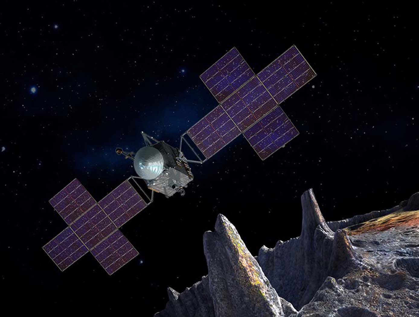
Modular Artificial-Gravity Orbital Refinery Spacecraft
Modular Artificial-Gravity Orbital Refinery Spacecraft is a solution for refining in-situ materials collected in space, such as from asteroids and Mars moons, as well as recycling spacecraft debris, while orbiting in micro-gravity conditions. The spacecraft is coupled with refining modules for refining and recycling different types of materials. It generates artificial gravity for operation in low-gravity environments. The spacecraft is comprised of rotating rings, each generating artificial gravity and angular momentum. When the rotating rings are combined on the spacecraft platform, however, they have a net near-zero angular momentum such that the spacecraft can change its attitude with minimal propellant or rotate at the rate of the object the spacecraft platform is attached to. The spacecraft platform can self-balance to accommodate different sized modules and modules with moving loads. The refined and recycled materials can be used to create products in-situ as well as products too large to launch from Earth, such as construction of orbiting space habitats, large spacecraft, solar-power stations, and observatories.
Sensors

Thin Film Sensor for Ultra High-Temp Measurement
The thin film sensor’s principal advantage lies in its potential to take high frequency temperature measurements from the surface of a reentering spacecraft while simultaneously withstanding the high temperature and oxidizing environment encountered. This data provides engineers with operational phase measurements used to refine the spacecraft’s operational envelope and track flight hardware behavior in addition to providing high frequency temperature measurements that can inform the physics of a boundary layer.
Mismatches in coefficients of thermal expansion (CTE) are expected in TPS-based sensor applications because the metallic materials used for temperature sensing have thermal expansion rates that differ from the rates of the substrate and coating materials in the TPS. At high temperatures during reentry, this mismatch in CTE can create a significant strain differential between the metallic sensor, sensor leads, and the materials to which the sensor and leads are bonded.
High frequency response temperature measurements on the surface of entry spacecraft are not currently possible above ~700 F with existing measurement capabilities. This shortcoming is primarily due to the need for robust sensor behavior at temperatures of several thousand degrees F. The sensor design of this technology preserves the integrity of sensor components while enhancing its high temperature functionality.
The thin film temperature sensor has a technology readiness level (TRL) 5 (Component and/or breadboard validation in relevant environment) and is now available for patent licensing. Please note that NASA does not manufacture products itself for commercial sale.
Materials and Coatings

Flexible Phenolic Intermingled Carbon Ablators (PICA-Flex)
Flexible PICAs combine both carbon and phenolic fiber constituents during a felting process rather than introducing a phenolic through infusion processes that also uses harsh chemicals. MERINO PICA-Flex materials drastically reduces integration complexities when compared to traditional phenolic infused rigid tiles, and can eliminate the costly and time intensive phenolic infusion process, resulting in a thermal protection system (TPS) material more akin to a “blanket” than a rigid TPS. PICA-Flex encompasses a range of configurations, including a dual layer PICA-Flex material with a higher density outer layer(s) to minimize recession, a lower density PICA-Flex material with applicability to aftbody TPS, and a single piece PICA-Flex forebody. PICA-Flex is fabricated by combining by intermingling both carbon and phenolic fiber constituents during a needle punch felting process during which the fibers are made into battings, and the battings are needled together layer-by-layer to build up thickness.
Materials and Coatings

Printable Heat Shield Formulations Advance Spacecraft Construction
One inner insulative layer, and one outer robust ablative layer comprise the AMTPS technology. When applying the heat shield to the surface of a spacecraft, the insulative layer is printed first and primarily functions to reduce the amount of heat soak into the vehicle. The formulation of the insulative layer has a slightly lower density (as compared to the robust layer) and is adjusted using a differing constituent ratio of phenolic and/or glass microballoon material. Both formulations combine a phenolic resin with various fillers to control pre- and post-cure properties that can be adjusted by varying the carbon and/or glass fiber content along with rheology modifiers to enhance the fluid flow for deposition systems.
The robust layer is applied next and functions as the ablative layer that ablates away or vaporizes when subjected to extremely high temperatures such as those achieved during atmospheric entry. The formulation of the robust layer produces a gas layer as it vaporizes in the extreme heat that acts as a boundary layer. This boundary prevents heat from further penetrating the remaining robust material by pushing away the even hotter shock layer. The shock layer is a region of super-heated compressed gas, positioned in front of the Earth-facing bottom of the spacecraft during atmospheric entry, that results from the supersonic shockwave generated.
Commercial space applications for this AMTPS technology include use on any spacecraft that transits a planetary or lunar atmosphere such as Mars or Saturn’s moon Titan. Additionally, the invention may be useful for launch system rockets to provide heat shielding from atmospheric reentry or to protect ground equipment on the launch pad from rocket exhaust plumes. As the number of government and commercial space missions to primary Earth orbits, the Moon, and the Solar System increase, there will be a growing need for cost-effective, on-demand, and timely fabrication of heat shields for space-related activities.
AMTPS Formulations – Insulative and Robust Variation is at a technology readiness level (TRL) 5 (component and/or breadboard validation in laboratory environment) and is now available for patent licensing. Please note that NASA does not manufacture products itself for commercial sale.

