AeroPod
aerospace
AeroPod (GSC-TOPS-10)
Aerodynamically stabilized instrument platform
Overview
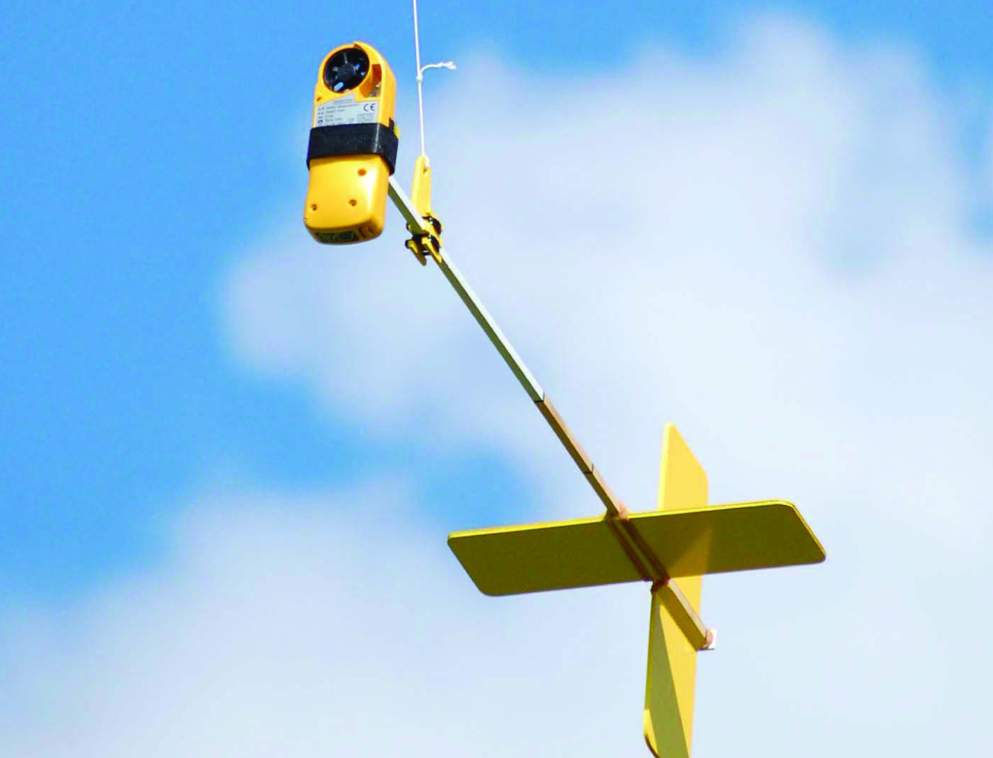
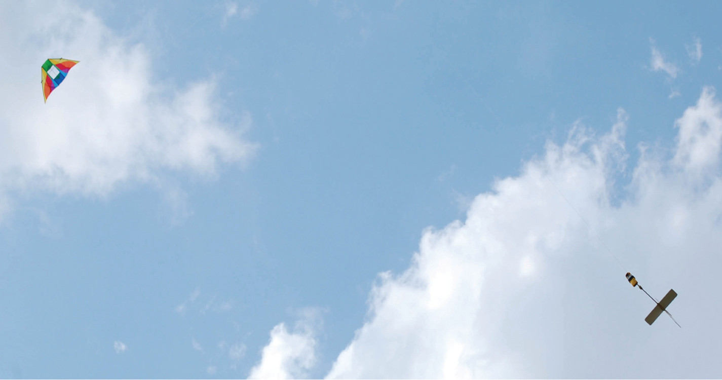
The AeroPod is a passive device that uses aerodynamic forces to stabilize an instrument package suspended from a kite or tethered blimp. It is a low-altitude custom remote sensing platform craft designed for, but not limited to, agricultural and environmental research purposes. AeroPods can be used for a variety of remote sensing and in-situ observations.
The Technology
The AeroPods design for steadying and damping payloads includes the use of a tail boom and fin combination. It is a novel design and provides a relatively simple alternative to the traditional methods for suspending equipment from kites or blimps.
The AeroPod is superior to the traditional Picavet pulley-style suspension system for kite-flight because its light weight, simple to construct, and has no moving parts. Furthermore, the AeroPod design is advantageous to the traditional tethered blimp suspension technique where tether motion is translated directly to the sensor system because the AeroPod is free of direct motions of the tether.


Benefits
- Light weight, simple to construct, and has no moving parts.
- Can be used for a variety of remote sensing and in-situ observations.
- Able to accommodate many different-sized instruments, even bulky ones.
- Offers a low-cost alternative to other remote sensing and observation techniques.
Applications
- Agricultural and environmental research purposes
- Observing and documenting forest canopy and cover
- Taking wetland studies
- Archeological and geological mapping
- Urban pattern mapping
- Crop monitoring
Similar Results

WindiWing: Atmospheric Data Collection Line Climber
This innovative kite system is called the WindiWing, and utilizes aerodynamic forces and moments to control its configuration for both ascent and descent, eliminating the need for an external power source or human intervention. By harnessing wind power, the system autonomously climbs and descends along a pilot kite line, provided sufficient wind conditions exist.
Windiwing includes a set of stops at predetermined upper and lower bounds of the kite line, which define the highest and lowest points the WindiWing can travel. When a stop is hit, the WindiWing changes direction. Therefore, it can sustain extended flight times at different altitudes. Unlike prior solutions, WindiWing is a passive line-climber operating entirely through aero-mechanical principles and does not require electrical power or active control systems for changes in lift. Instead, WindiWing continuously moves between the designated stops along the kite tether, maintaining stable and predictable movement without the need for remote operation or onboard power.
WindiWing is designed with flexibility in mind, offering the ability to carry a range of instrumentation, making it suitable for integration with kite-based systems, tethered balloons, or uncrewed aircraft platforms. The absence of electrical components reduces complexity, enhances reliability, and allows for extended atmospheric data collection with minimal oversight.
By offering a scalable, cost-effective, and power-independent solution, this technology enables long-duration atmospheric profiling at various altitudes, making it an ideal tool for researchers in the fields of atmospheric research, environmental research, and education.

Powered Kite with Enhanced Aerial Position Control
Skyvator offers enhanced positional capabilities. Skyvator can perform maneuvers such as pointing into or perpendicular to the wind, maintaining level flight, climbing, descending, and station-keeping at desired altitudes. These movements are enabled by the power system, incorporated in the wing or other location on the kite, which are attached to the controller, and in turn is connected to one or more actuators, such as motors and drivers. These motors and drivers can be located in various portions of the kite to cause one part or another to move. Additionally, the controller can be connected to one or more instrument systems for data collection and measurement purposes. These include sensors for detecting windspeed, direction, pressure, GPS, temperature, humidity, imagers, atmospheric particle detectors, and gas detectors, among others. The improved positional control and information allows a user to collect data more effectively and accurately.Skyvator is designed to be used across a wide range of altitudes, from a few feet above the ground to over 18,000 feet above the surface. Additionally, Skyvator prototypes have demonstrated the ability to maintain stready, controllable flight exceeding 60 – 70 mph winds. Please note that NASA does not manufacturer products itself for commercial sale.

Low Weight Flight Controller Design
Increasing demand for smaller UAVs (e.g., sometimes with wingspans on the order of six inches and weighing less than one pound) generated a need for much smaller flight and sensing equipment. NASA Langley's new sensing and flight control system for small UAVs includes both an active flight control board and an avionics sensor board. Together, these compare the status of the UAVs position, heading, and orientation with the pre-programmed data to determine and apply the flight control inputs needed to maintain the desired course.
To satisfy the small form-factor system requirements, micro-electro-mechanical systems (MEMS) are used to realize the various flight control sensing devices. MEMS-based devices are commercially available single-chip devices that lend themselves to easy integration onto a circuit board. The system uses less energy than current systems, allowing solar panels planted on the vehicle to generate the systems power. While the lightweight technology was designed for smaller UAVs, the sensors could be distributed throughout larger UAVs, depending on the application.

Adaptive wind estimation for small unmanned aerial systems using motion data
The technology presents an on-board estimation, navigation and control architecture for multi-rotor drones flying in an urban environment. It consists of adaptive algorithms to estimate the vehicle's aerodynamic drag coefficients with respect to still air and urban wind components along the flight trajectory, with guaranteed fast and reliable convergence to the true values. Navigation algorithms generate feasible trajectories between given way-points that take into account the estimated wind. Control algorithms track the generated trajectories as long as the vehicle retains a sufficient number of functioning rotors that are capable of compensating for the estimated wind. The technology provides a method of measuring wind profiles on a drone using existing motion sensors, like the inertial measurement unit (IMU), rate gyroscope, etc., that are observably necessary for any drone to operate. The algorithms are used to estimate wind around the drone. They can be used for stability or trajectory calculations, and are adaptable for use with any UAV regardless of the knowledge of weight and inertia. They further provide real-time calculations without additional sensors. The estimation method is implemented using onboard computing power. It rapidly converges to true values, is computationally inexpensive, and does not require any specific hardware or specific vehicle maneuvers for the convergence. All components of this on-board system are computationally effective and are intended for a real time implementation. The method's software is developed in a Matlab/Simulink environment, and has executable versions, which are suitable for majority of existing onboard controllers. The algorithms were tested in simulations.

Small Compound-Wing VTOL UAS
This UAS technology defines a part-time VTOL system that transitions to efficient fixed-wing operation to obtain desired endurance and range. A novel three-segment wing design includes: a fixed Inner segment mounted to the fuselage, a controlled, articulating intermediate segment to which lift engines are attached, and a free-to-rotate outer segment to alleviate gust impacts on the airframe in both modes. The aft propulsor is articulated and configured such that the thrust being generated is always in a proverse direction. Also, the controlled-articulation wing segments are operated in both tandem and differential modes to allow for direct control while in the various modes of operation. Also incorporated is a novel control architecture that encompasses both the different system operating modes as well as the considerable number of individual control options and combinations.


