New motors for next-generation in-space servicing
Robotics Automation and Control
New motors for next-generation in-space servicing (GSC-TOPS-351)
Innovative components for the Advanced Tool Drive System
Overview
Brushless direct current (BLDC) motors are of interest to drive tools for in-space servicing due to their reliability, efficiency, and controllability. Current BLDC motors do not meet the needs of space environments, nor do they have common interfaces, limiting their versatility.
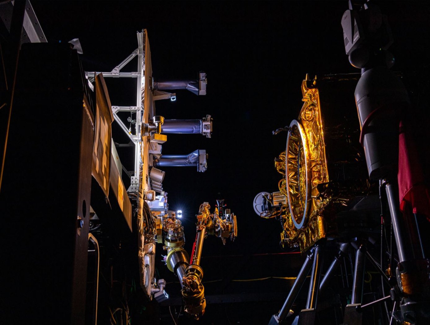
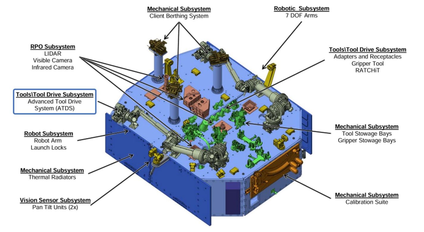
NASA inventors have developed four BLDC motors to power a variety of tools for in-space servicing. The motors are part of the Advanced Tool Drive System (ATDS) that is attached to the end of a robotic arm providing the power for the servicing tools. While the motors have differing performance characteristics to drive various tools, they have been designed with a common gearhead for versatility within a single frame size. The motors are built to withstand the wide temperature variations and radiation conditions of geosynchronous orbit.
The BLDC motors and the ATDS will be used for spacecraft servicing in manned and unmanned missions and may also apply to terrestrial robotic systems.
The Technology
Satellites and other spacecraft require maintenance and service after being deployed in orbit, requiring a wide variety of tools that perform multiple maintenance tasks (grip, cut, refuel, etc.). Current drive systems for the tool interfaces on the robotic arms that perform these service tasks are not as robust nor packaged properly for use in the ATDS. The ATDS is one part of a larger in-space servicing system (example shown in the figure below) that must be versatile and perform multiple jobs.
Here, innovators at the NASA Goddard Space Flight Center have developed new BLDC motors to provide the torque necessary to drive the wide variety of tools needed for in-space servicing. The four motors provide torque to the coupler drive, linear drive, inner rotary drive, and outer rotary drive of the ATDS. The new BLDC motors will enable the tools attached to the ATDS to be operated in multiple modes of operation.
Each of the four motors have been customized with different speed and torque capabilities to meet the different performance requirements of the various actuator drive trains while maintaining a common gearhead across all the motors. Further, the packaging surrounding the motors has been tailored to reduce the overall weight of the motors and reduce the motor footprint to meet the needs of the ATDS. The BLDC motors for the ATDS are available for patent licensing.


Benefits
- Robust: Built to survive the harsh environment (temperature variations and high levels of radiation) of geosynchronous earth orbit
- Lightweight and smaller footprint: The new ATDS motor system is smaller and lighter than previous or commercially available BLDC motors
- Multipurpose: the BLDC motors can power multiple tools for in-space servicing
- Customizable: the BLDC motors can be further customized and developed for changing load, speed, and torque requirements
Applications
- In-space servicing and assembly: the BLDC motors can be used to drive tools for servicing (and assembly) of spacecraft in orbit
- Terrestrial robotics and automation: these motors may also be used for robotic or automated manufacturing processes terrestrially
Technology Details
Robotics Automation and Control
GSC-TOPS-351
GSC-16872-1
|
Tags:
|
Similar Results

Precision Low Speed Motor Controller
The Precision Low Speed Motor Controller was designed as part of an OpTIIX telescope for the International Space Station. This technology is based on a precise current control loop and a high fidelity velocity measurement algorithm. The precise current loop uses a mathematical model of the electrical dynamics of the motor, custom electronics, and a PI controller to maintain a rapid response and smooth current control. The velocity measurement algorithm is embedded in the velocity loop that is wrapped around the current loop to provide a smooth low velocity control.
Current motors are only capable of operating at approximately 15 rpm with a risk of excessive jitters. This technology reduces the responsive rpms by several orders of magnitude to approximately 0.025 rpms. This technology's capability has been integral to the success of several NASA projects, such as the OpTIIX telescope, the NASA Robonaut 2 robot , and the Modular Robotic Vehicle (MRV).

High Efficiency Megawatt Motor
The HEMM is a is a wound-field partially superconducting machine that implements a combination of rotor superconducting and stator normal conductor elements, along with an integrated acoustic cryocooler, to achieve some of the benefits of a superconducting motor without the need for an external cryogenic system. The combination of the described elements allows a motor to be built which essentially operates like any other motor when viewed as a black box, but substantially enhanced performance can be achieved. The incorporation of superconductors on the rotor to create a high-level magnetic field results in a specific power and efficiency that could not be achieved any other way. The HEMM can achieve over 98% efficiency in a lightweight electric machine with an operating power greater than 1.4 MW, a specific power greater than 16 kW/kg (ratio to electromagnetic mass), and a rated operating speed of 6800 RPM. The HEMM can be used as both a motor or a generator, offering a wide range of applications including propulsion systems for hybrid aircraft, electric trains, hybrid cars, and turboelectric ships, as well as generator systems for wind turbines, power plants, or motors for other industrial machinery.

Internal Friction Reduction (IFR) Tool
During SR-FSW, the wicking of substrate material into the gap between the crown shoulder and pin can lead to pinch load shifting–an increasing difference between the applied pin load and actual pinch load. NASA's IFR Tool mitigates pinch load shifting, enabling a more robust SR-FSW process due to better agreement between the applied pin load and the actual pinch load.
As pinch loads are not dynamically measured during welding, NASA has relied on defect rates and pin tool ejection loads to demonstrate the value of the IFR Tool. Large-scale welds were performed with both the IFR Tool and a standard pin tool. Weld inspections found a 90% reduction in defect generation rate for the IFR tool, and the first defect in the standard pin tool sample occurred at 300" compared to at 900" in the IFR Tool sample. There was also a drastic improvement in mechanical properties variations along the weld.
In another study, a series of 27.5' barrel welds were performed with both the IFR Tool and a standard pin tool. After welding, ejection forces required to remove the pin tools from their fixtures were measured. The standard pin tool ejection force was 9,400 lbs., nearly 5 times larger than that of the IFR Tool at 2,000 lbs . The large difference suggests that during welding, the standard pin tool would have been less responsive to substrate surface variations than the IFR Tool. Weld inspections supported this theory, as they found a significantly lower defect rate in the IFR Tool samples.

Anode Manifold Plug for Hall Effect Thrusters
Flow-restricting features in a Hall thruster anode manifold assembly, typically precision manufactured orifices, can contribute to significant flow non-uniformity if tolerances on the features are not properly controlled. Non-uniformity in flow distribution negatively impacts thruster performance. The anode assembly is usually a complex and expensive assembly to manufacture. Removing the flow restricting elements from the anode manifold structure in favor of modular insertable subcomponents (i.e., plugs) enables the use of more reliable and repeatable precision manufacturing techniques. The resulting components can be tested, characterized, and sorted for acceptance before being installed into the larger anode assembly (i.e., quality control can be performed at the subcomponent level). This may lead to increased performance and yield rate of the final assembly.
The flow restrictor plugs can be made in many different ways. The most basic flow restrictor takes the form of a precision hole machined into a cylinder, where the cylinder is then press fit into a hole drilled into the anode base. Alternate embodiments of the flow restrictor include precision machined nozzles, laminar flow elements, or sintered porous metal elements. The flow restrictor can also be made from a different material than the anode base, such as a precision ruby orifice contained in a metal carrier which is installed in a metal anode base. The plugs can be installed in a variety of ways, all of which create hermetic seals. Installation can include a press fit relying on plastic deformation or threading the plug component into the anode base. Welding on the top surface of the anode base can also be done to provide a robust hermetic seal.

Fast-Acting, Deep-Throttling Hybrid Motor
Hybrid chemical motors offer an alternative to traditional liquid or solid motors for spacecraft, missiles, rockets, or other vehicles. The key advantage of a hybrid motor is the capability to throttle the motor via active control, which cannot be done in solid propellant motors. However, rapid throttling presents significant challenges to implement in practice.
Here, NASA has combined a deep-throttling hybrid motor previously developed by Utah State University with a fast-acting digital valve design to produce a fast-acting, deep-throttling hybrid. Testing performed to-date using a prototype of the hybrid motor and digital valve design has shown the new hybrid motor to be capable of full-scale throttling twice as fast (1 second throttling compared to 2 seconds) as previous control valve designs. With optimization, there is potential full-range throttling may be further reduced to 0.5 second, a 4x improvement over previous control valve designs for hybrid motors. Additionally, smaller mid-range thrust changes have currently been measured in the 40:1 for relatively small motors (


