Search
aerospace
Dynamic Weather Routes Tool
Every 12 seconds, the Dynamic Weather Route (DWR) automation system computes and analyzes trajectories for en-route flights. DWR first identifies flights that could save 5 or more flying minutes (wind-corrected) by flying direct to a downstream return fix on their current flight plan. Eligible return fixes are limited so as not to take flights too far off their current route or interfere with arrival routings near the destination airport. Using the direct route as a reference route, DWR inserts up to two auxiliary waypoints as needed to find a minimum-delay reroute that avoids the weather and returns the flight to its planned route at the downstream fix. If a reroute is found that can save 5 minutes or more relative to the current flight plan, the flight is posted to a list displayed to the airline or FAA user. Auxiliary waypoints are defined using fix-radial-distance format, and a snap to nearby named fix option is available for todays voice-based communications. Users may also adjust the alert criteria, nominally set to 5 minutes, based on their workload and desired potential savings for their flights. A graphical user interface enables visualization of proposed routes on a traffic display and modification, if necessary, using point, click, and drag inputs. If needed, users can adjust the reroute parameters including the downstream return fix, any inserted auxiliary waypoints, and the maneuver start point. Reroute metrics, including flying time savings (or delay) relative to the current flight plan, proximity to current and forecast weather, downstream sector congestion, traffic conflicts, and conflicts with special use airspace are all updated dynamically as the user modifies a proposed route.
electrical and electronics
SpaceCube
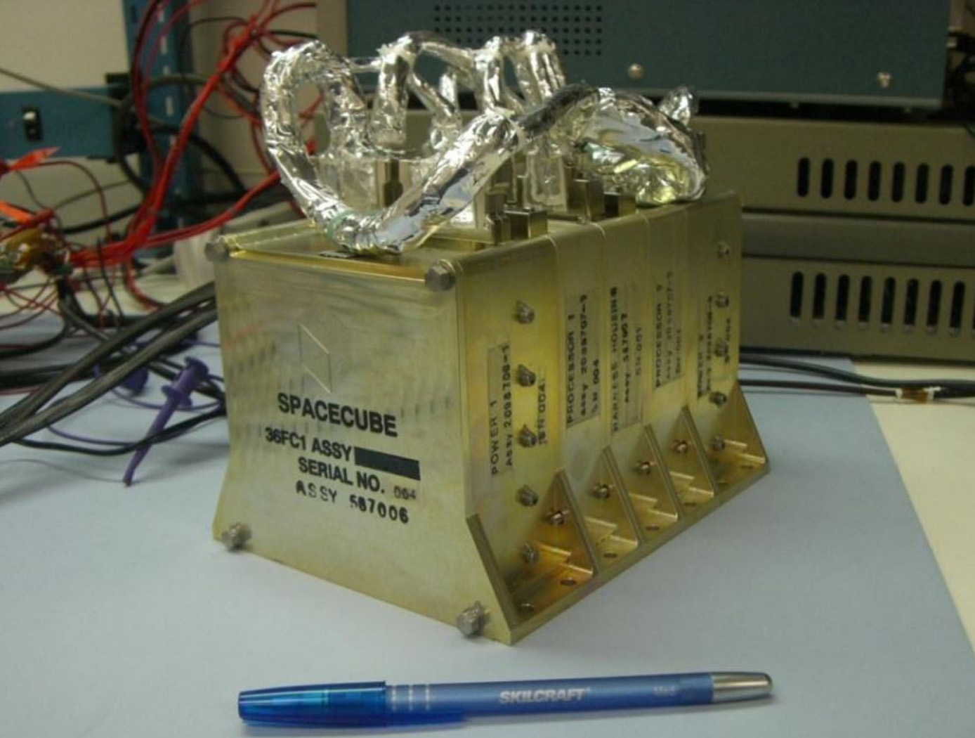
Next generation instruments are capable of producing data at rates of 108 to 1011 bits per second, and both their instrument designs and mission operations concepts are severely constrained by data rate/volume. SpaceCube is an enabling technology for these next generation missions.
SpaceCube has demonstrated enabling capabilities in Earth Science, Planetary, Satellite Servicing, Astrophysics and Heliophysics prototype applications such as on-board product generation, intelligent data volume reduction, autonomous docking/landing, direct broadcast products, and data driven processing with the ability to autonomously detect and react to events. SpaceCube systems are currently being developed and proposed for platforms from small CubeSats to larger scale experiments on the ISS and standalone free-flyer missions, and are an ideal fit for cost constrained next generation applications due to the tremendous flexibility (both functional and interface compatibility) provided by the SpaceCube system.
Environment
Robonaut 2: Hazardous Environments
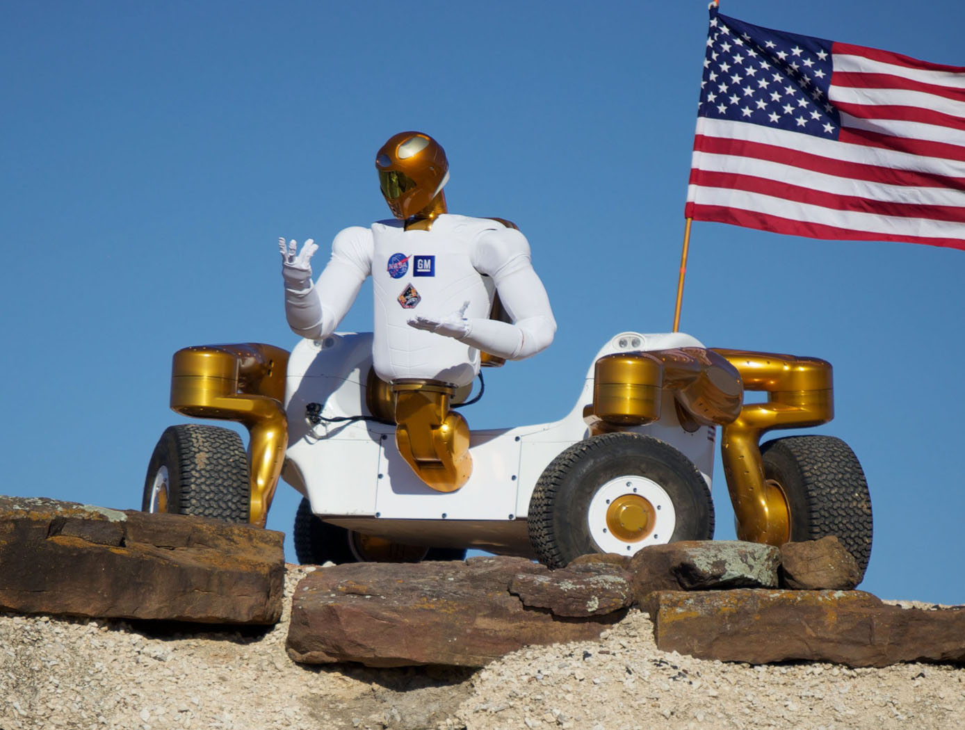
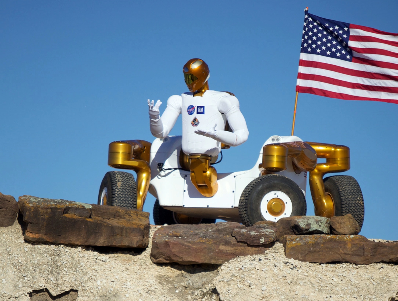
Robonaut 2 (R2) has the capability of functioning autonomously or it can be controlled by direct teleoperations, which is advantageous for hazardous environments. When functioning autonomously, R2 understands what to do and how to do it based on sensory input. R2's torso holds the control system while the visor holds several cameras that are incorporated into the visual perception system. With these capabilities, R2 can reduce or eliminate the need for humans to be exposed to dangerous environments. R2 also has a very rugged four-wheel base called the Centaur 2. The Centaur 2 base can lower or raise itself to and from the ground and turn its wheels in any direction, allowing it to turn in place and drive forward or sideways. This enables the R2 to enter hazardous areas or tackle difficult terrain without endangering its human operator.
Robonaut 2 as a whole, or some of its components, can be an invaluable tool for land mine detection, bomb disposal, search and rescue, waste recycling, medical quarantined area, and so much more. The suite of technologies provides an ability to manipulate tools to help with a task, or it can tackle many tasks in a row, where a standard robot may not have the dexterity or sensing capability to get the job done. R2 could pick through nuclear waste, measure toxicity levels, and survey areas too remote or dangerous for human inspection. R2 could deal with improvised explosive devices, detect and dispose of bombs or landmines, and operate equipment that can break through walls or doors.
Manufacturing
Robonaut 2: Industrial Opportunities
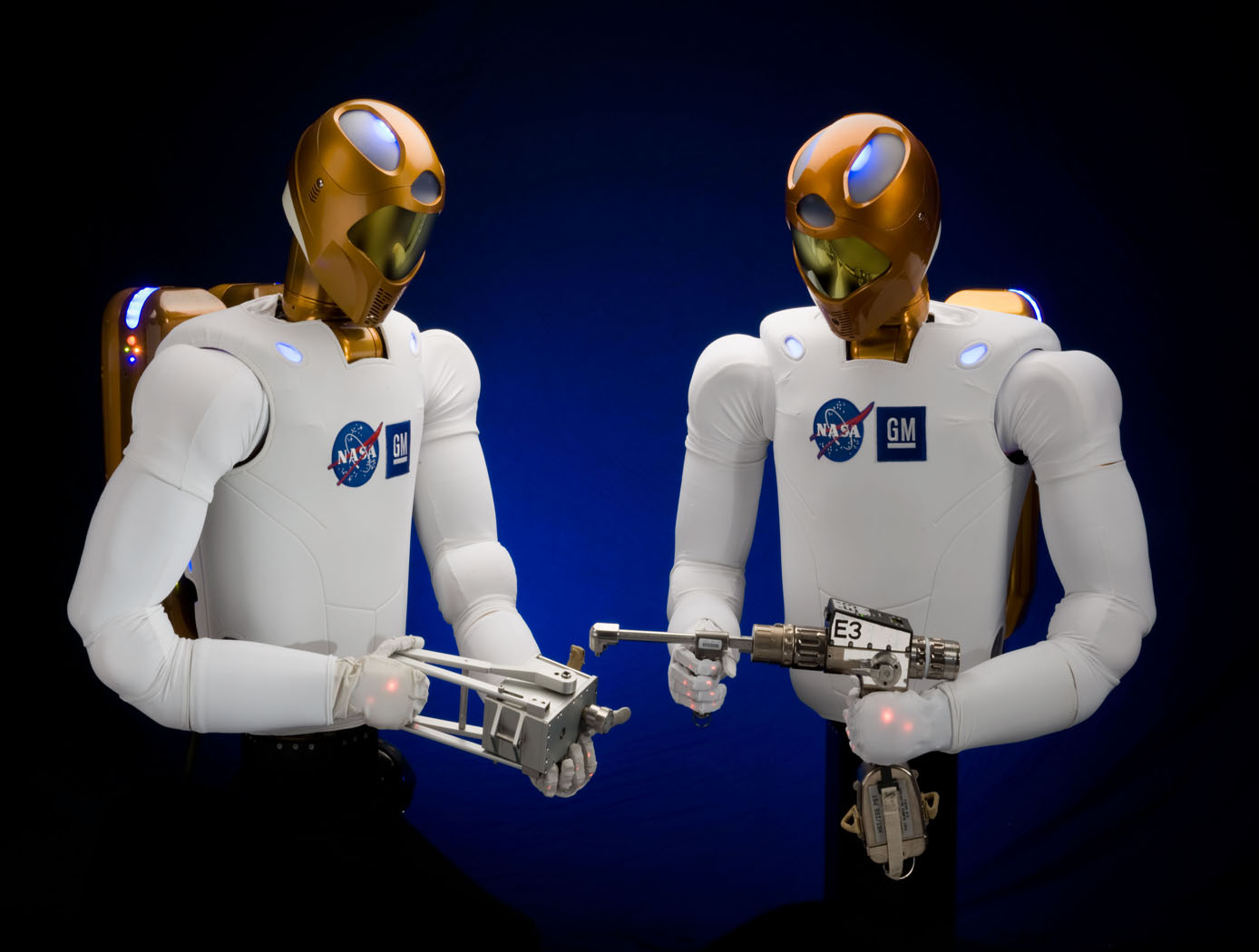
NASA, GM, and Oceaneering approached the development of R2 from a dual use environment for both space and terrestrial application. NASA needed an astronaut assistant able to function in space and GM was looking for a robot that could function in an industrial setting. With this in mind, R2 was made with many capabilities that offer an enormous advantage in industrial environments. For example, the robot has the ability to retool and vary its tasks. Rather than a product moving from station to station on a conveyor with dozens of specialized robots performing unique tasks, R2 can handle several assembly steps at a single station, thereby reducing manufacturing floor space requirements and the need for multiple robots for the same activities. The robot can also be used in scenarios where dangerous chemicals, biological, or even nuclear materials are part of the manufacturing process.
R2 uses stereovision to locate human teammates or tools and a navigation system. The robot was also designed with special torsional springs and position feedback to control fine motor movements in the hands and arms. R2's hands and arms sense weight and pressure and stop when they come in contact with someone or something. These force sensing capabilities make R2 safe to work side-by-side with people on an assembly line, assisting them in ergonomically challenging tasks or working independently.
This NASA Technology is available for your company to license and develop into a commercial product. NASA does not manufacture products for commercial sale.
manufacturing
.jpg)
Interim, In Situ Additive Manufacturing Inspection
The in situ inspection technology for additive manufacturing combines different types of cameras strategically placed around the part to monitor its properties during construction. The IR cameras collect accurate temperature data to validate thermal math models, while the visual cameras obtain highly detailed data at the exact location of the laser to build accurate, as-built geometric models. Furthermore, certain adopted techniques (e.g., single to grouped pixels comparison to avoid bad/biased pixels) reduce false positive readings.
NASA has developed and tested prototypes in both laser-sintered plastic and metal processes. The technology detected errors due to stray powder sparking and material layer lifts. Furthermore, the technology has the potential to detect anomalies in the property profile that are caused by errors due to stress, power density issues, incomplete melting, voids, incomplete fill, and layer lift-up. Three-dimensional models of the printed parts were reconstructed using only the collected data, which demonstrates the success and potential of the technology to provide a deeper understanding of the laser-metal interactions. By monitoring the print, layer by layer, in real-time, users can pause the process and make corrections to the build as needed, reducing material, energy, and time wasted in nonconforming parts.
Robotics Automation and Control
New motors for next-generation in-space servicing
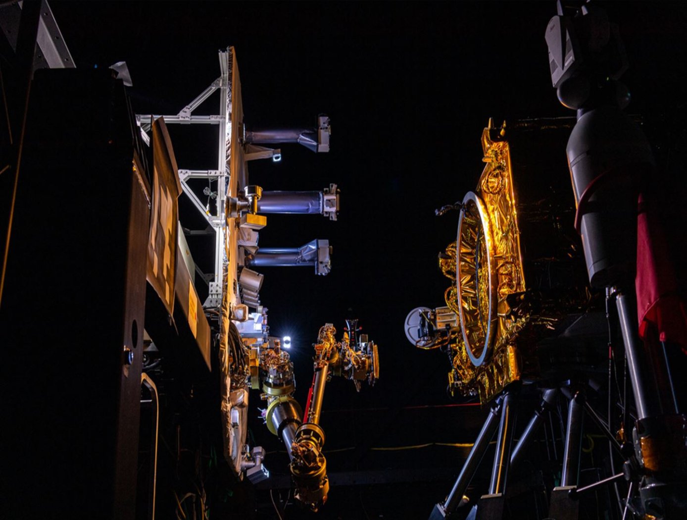
Satellites and other spacecraft require maintenance and service after being deployed in orbit, requiring a wide variety of tools that perform multiple maintenance tasks (grip, cut, refuel, etc.). Current drive systems for the tool interfaces on the robotic arms that perform these service tasks are not as robust nor packaged properly for use in the ATDS. The ATDS is one part of a larger in-space servicing system (example shown in the figure below) that must be versatile and perform multiple jobs.
Here, innovators at the NASA Goddard Space Flight Center have developed new BLDC motors to provide the torque necessary to drive the wide variety of tools needed for in-space servicing. The four motors provide torque to the coupler drive, linear drive, inner rotary drive, and outer rotary drive of the ATDS. The new BLDC motors will enable the tools attached to the ATDS to be operated in multiple modes of operation.
Each of the four motors have been customized with different speed and torque capabilities to meet the different performance requirements of the various actuator drive trains while maintaining a common gearhead across all the motors. Further, the packaging surrounding the motors has been tailored to reduce the overall weight of the motors and reduce the motor footprint to meet the needs of the ATDS. The BLDC motors for the ATDS are available for patent licensing.
sensors
Super Resolution 3D Flash LIDAR
This suite of technologies includes a method, algorithms, and computer processing techniques to provide for image photometric correction and resolution enhancement at video rates (30 frames per second). This 3D (2D spatial and range) resolution enhancement uses the spatial and range information contained in each image frame, in conjunction with a sequence of overlapping or persistent images, to simultaneously enhance the spatial resolution and range and photometric accuracies. In other words, the technologies allows for generating an elevation (3D) map of a targeted area (e.g., terrain) with much enhanced resolution by blending consecutive camera image frames. The degree of image resolution enhancement increases with the number of acquired frames.
Instrumentation
Cryostat-500
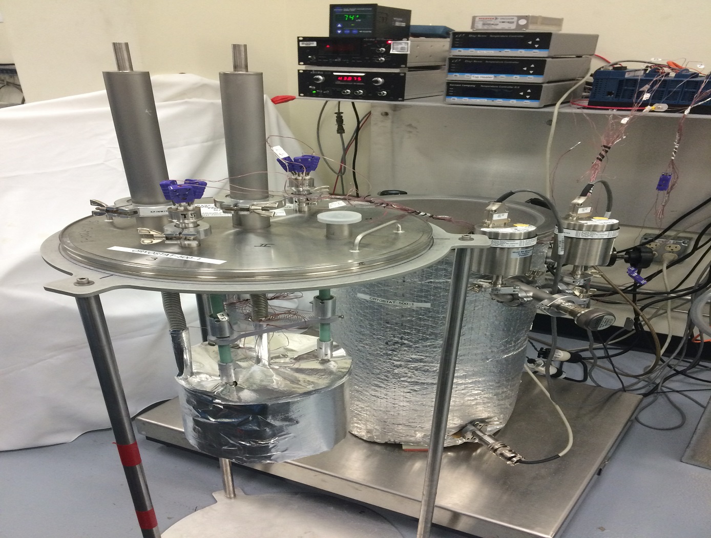
The Cryostat-500 provides laboratory measurement of the steady-state thermal transmission properties of thermal insulation systems under conditions below ambient temperature. Liquid nitrogen is used as a direct measure of the energy going through the test specimen. Thermal insulation systems may be composed of one or more materials that may be homogeneous or non-homogeneous at boundary conditions from 77 K to 373 K and in environments from high vacuum (10E-7 torr) to ambient pressure (10E+3 torr).
The Cryostat-500 provides a much wider range of thermal performance and covers the full range of environmental conditions for applications below ambient temperature. The instrument has been proven through extensive testing of foams, composite panels, multilayer insulation (MLI) systems, aerogel blankets, fiberglass, and many other types of materials. Both the quality and quantity of the thermal performance data for insulation materials and systems have increased even as the process and method has become more time efficient and cost effective. Further guidelines on the test method and equipment for the Cryostat-500 are given in ASTM C1774, Annex A3.
Mechanical and Fluid Systems
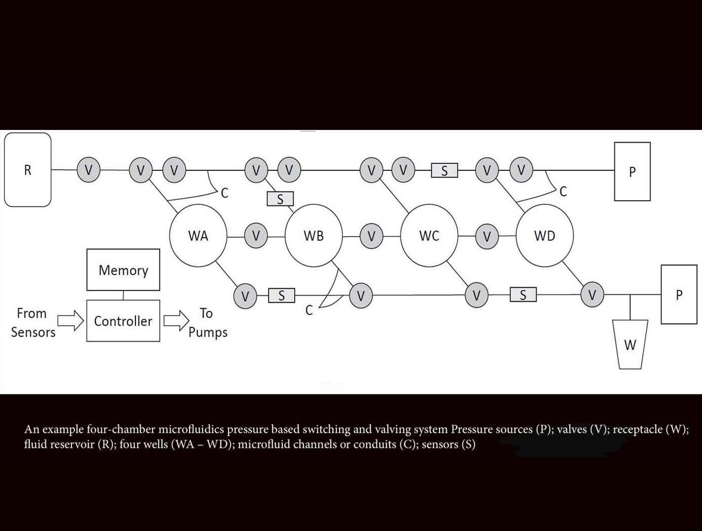
Microfluidics Pressure-Based Switching and Valving Array
The innovative technology from Ames acts as a microfluidics switch array, using combinations of pressure and flow conditions to achieve specific logic states that determine the sequences of sample movement between microfluidic wells. This advancement will enable automation of complex laboratory techniques not possible with earlier microfluidics technologies that are designed to follow predetermined flow paths and well targets. This novel method also enables autonomous operations including changing the flow paths and targeting well configurations in situ based on measured data decision parameters. This microfluidic system can be reconfigured for use in various experimental applications, requiring only an adjustment of the programmed pressure sequencing, reducing the need for custom design and development for each new application. For example, this technology could provide the ability to selectively constrain or move biological specimens in the experimental wells, allowing evolutionary studies of model organisms in response to various stressors, evaluation of different growth conditions on biological production of antibodies or other small molecule therapeutics, among other potential applications. Likewise, this platform can be used to foster time-dependent, step-wise, chemical reactions, which could be used for novel chemical processes or in situ resource utilization.
environment
Closed Ecological System Network Data Collection, Analysis, Control, and Optimization System
The technology relates generally to controlled ecosystems, and more particularly, to a Controlled Closed-Ecosystem Development System (CCEDS) that can be used to develop designs for sustainable, small-scale reproductions of subsets of the Earths biosphere and the Orbiting Modular Artificial-Gravity Spacecraft (OMAGS). The technology encompassing a CCEDS includes one or more a Closed Ecological Systems (CESs), each having one or more Controlled Ecosystem Modules (CESMs). Each CESM can have a biome containing at least one organism, and equipment comprising one or more of sensors, actuators, or components that are associated with the biome. A controller operates the equipment to effect transfer of material among CESMs to optimize one or more CESM biomes with respect to their organism population health, resilience, variety, quantities, biomass, and sustainability. A CES is a community of organisms and their resources that persist in a sealed volume such that mass is not added or removed. The mass (food/air/water) required by the CES organisms is continually recycled from the mass (waste) produced by the organisms. Energy and information may be transferred to and from a CES. CES research promises to become a significant resource for the resolution of global ecology problems which have thus far been experimentally inaccessible and may very well prove an invaluable resource for predicting the probable ecological consequences of anthropogenic materials on regional ecosystems. In order to create CESs that are orders of magnitude smaller than the Earth that can function without the Earth, the desired gravity level and necessary radiation shielding must be provided by other means. Orbiting Modular Artificial-Gravity Spacecraft (OMAGS) is a fractional gravity spacecraft design for CES payloads and is depicted in Figures below. In tandem, the CCEDS and OMAGS systems can be used to foster gravitational ecosystem research for developing sustainable communities in space and on Earth.

