A Portable Impactor Device
Manufacturing
A Portable Impactor Device (LAR-TOPS-114)
Lightweight instrument for investigating structural response
Overview
NASA's Langley Research Center has developed a portable device to simulate low-velocity impacts on a material or structure. As composite materials are highly susceptible to damage caused by low-velocity impact, they must be designed and evaluated for structural integrity after these types of impacts.
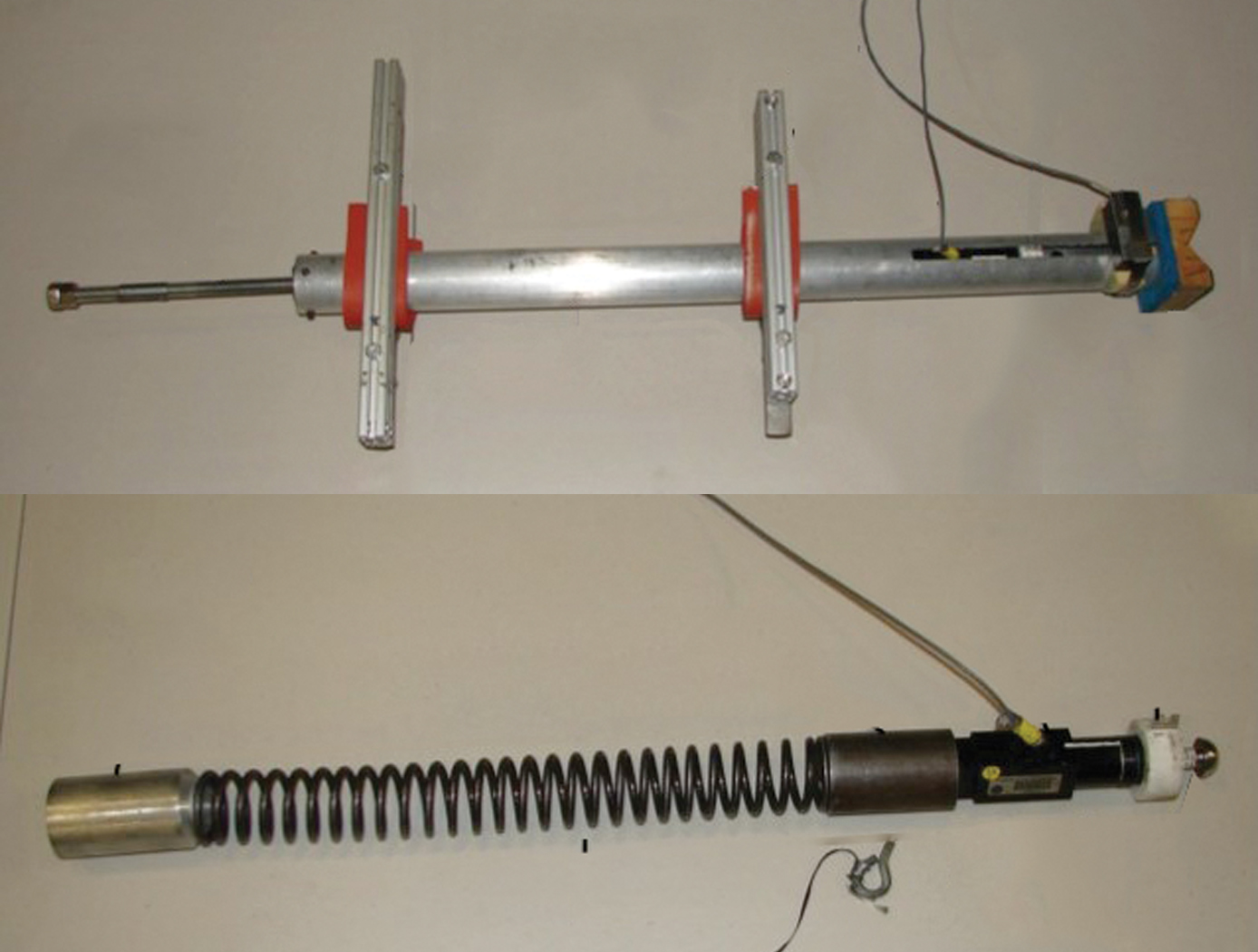
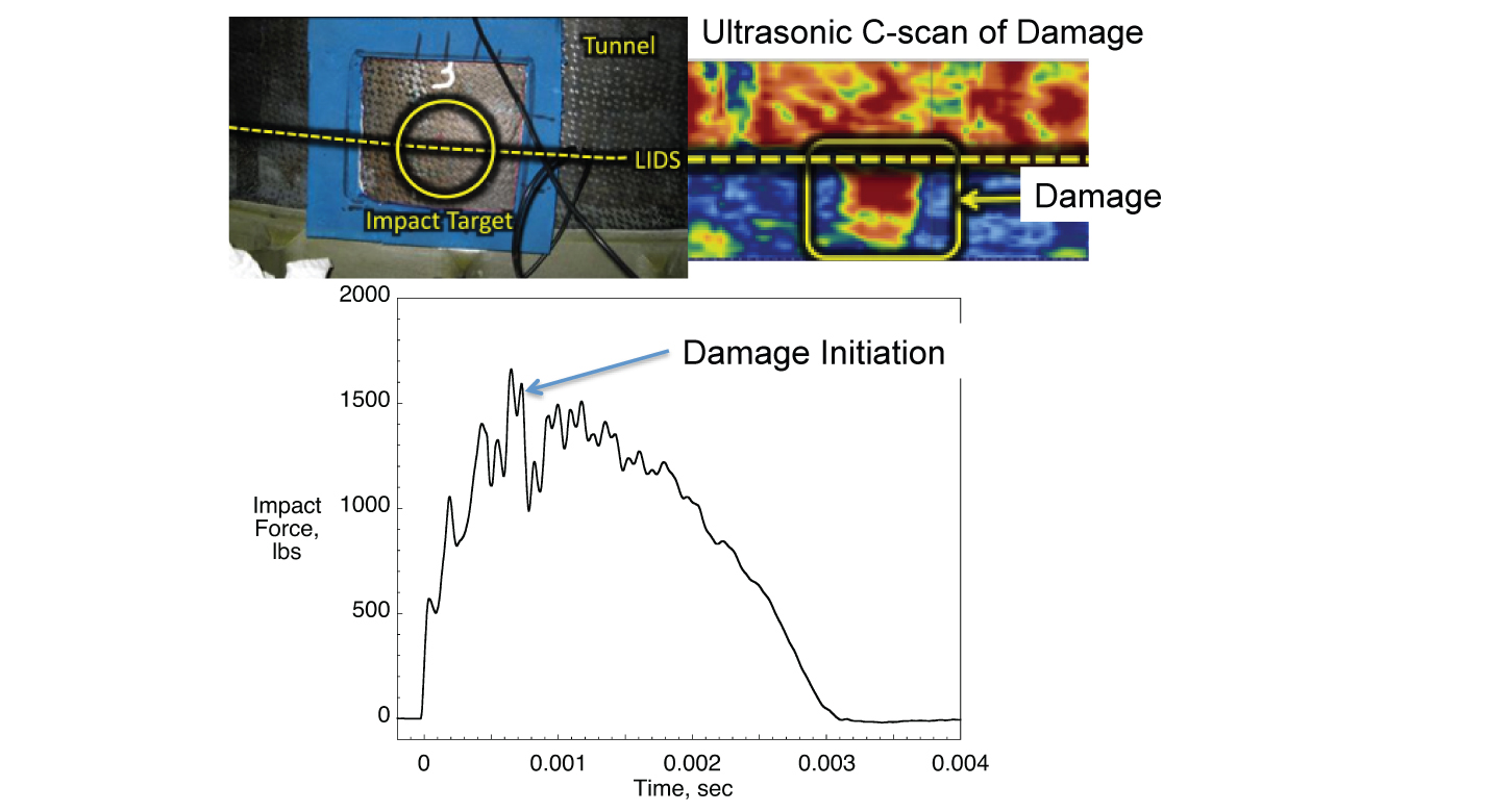
The NASA impactors design comprises an exterior tube, an instrumented projectile, a spring to propel the projectile, a spring compression device, a release pin, a wooden spacer/locator block, and an optical sensor.The tube can be handheld or rigidly mounted at any angle such that the impact response can be evaluated at specific positions on the test article. In the current configuration, impact energies between 4 and 40 J (between about 3 and 30 ft-lbs) can be obtained. Researchers designed a fully functioning prototype for the NASA Engineering and Safety Centers (NESCs) Composite Crew Module (CCM) program for damage tolerance testing. Both the impact force history and projectile velocity are captured during operation.
The Technology
The NASA impactor is a fully portable device that propels an instrumented projectile so that it impacts a vehicle, structural component, or test specimen. The device includes a projectile inside an exterior tube. The projectile itself contains a commercial load cell designed to obtain the dynamic force response during the impact event. Furthermore, a digital oscilloscope and optical sensor are combined to measure the velocity just prior to impact so that the impact energy of the projectile onto the test surface can be calculated. In the current configuration, impacts with energies between 4 and 40 J (between about 3 and 30 ft-lbs) are obtainable, and could be adjusted by changing the spring to one with a different spring constant. The tube can be handheld
or rigidly mounted at any angle such that the impact response can be evaluated at specified positions throughout the test article. The impactor device is primarily designed for use on composite structures to investigate the structural response from a low-velocity impact, as composite materials are highly susceptible to damage from low-velocity impacts where the damage may not be visible but results in great loss of strength. If the damage cannot be detected visually, it can be seen through nondestructive testing (ultrasonic, flash thermography or X-ray). However, the device may also be used on structures to evaluate and tune structural health monitoring systems.
The technology has been designed, prototyped, and implemented in four military
or government programs for impact testing on metallic and composite structures,
including a helicopter roof in 2013. The cost of the parts for the prototype was
approximately $9,000. Production costs are expected to be lower.


Benefits
- Portable - can be handheld or clamped into position.
- Lightweight - weighs approximately 15 lbs.
- Controlled uses a spring rather than gravity to propel projectile.
- Variable is not dependent on specimen size or orientation.
- Adaptable - spring can be changed to reach desired impact energies.
- Easy to use - has a straightforward design.
- Proven - has been prototyped and tested in various NASA and U.S. Army applications.
Applications
- Aerospace - investigating impact damage resistance or tolerance of small coupons or large structures
- Aviation - testing structural health of existing vehicles
- Automotive - assessing durability and damage tolerance of metallic or composite parts
Technology Details
Manufacturing
LAR-TOPS-114
LAR-18411-1
Use of a New Portable Instrumented Impactor on the NASA Composite Crew Module Damage Tolerance Program, Wade C. Jackson, Proceedings of the American Society for Composites 29th Conference and 16th US-Japan Conference and ASTM D30 Meeting, https://ntrs.nasa.gov/api/citations/20140016384/downloads/20140016384.pdf
|
Tags:
|
Similar Results
Multidimensional Damage Detection System
The Damage Detection System consists of layered composite material made up of two-dimensional thin film damage detection layers separated by thicker, nondetection layers, coupled with a detection system. The damage detection layers within the composite material are thin films with a conductive grid or striped pattern. The conductive pattern can be applied on a variety of substrates using several different application methods. The number of detection layers in the composite material can be tailored depending on the level of damage detection detail needed for a particular application. When damage occurs to any detection layer, a change in the electrical properties of that layer is detected and reported. Multiple damages can be detected simultaneously, providing real-time detail on the depth and location of the damage.
The truly unique feature of the System is its flexibility. It can be designed to gather as much (or as little) information as needed for a particular application using wireless communication. Individual detection layers can be turned on or off as necessary, and algorithms can be modified to optimize performance. The damage detection system can be used to generate both diagnostic and prognostic information related to the health of layered composite structures, which will be essential if such systems are utilized to protect human life and/or critical equipment and material.

Multi-layered Self-healing Material System for Impact Mitigation
This innovation utilizes a tri-layered structure, comprised of solid plastic front and back layers sandwiching a viscous, reactive liquid middle layer. Combined, this system provides rapid self-healing following high velocity ballistic penetrations. Self-healing in the front and back layers occurs when the puncture event creates a melt state in the polymer materials and the materials melt elasticity snaps back and closes the hole. The viscous middle layer augments the self-healing properties of the other layers by flowing into the gap created by a ballistic puncture and concurrently solidifying due to the presence of oxygen. Thus, this innovation has two tiers of self-healing: a puncture-healing mechanism triggered by the projectile and a second mechanism triggered by the presence of oxygen.
MMOD Impact Detection and Location
Multiple strain sensors encoded into one or more optical fibers are affixed to a MMOD shield or structure. The optical fiber(s) is/are connected to a data collection device that records strain data at a frequency sufficient to resolve MMOD impact events. Strain data are processed and presented on a computer display. MMOD impact imparts a transient shock loading to a structure which is manifested as transient strain as the shock wave moves through the structure. MMOD impacts are determined from the time signature of, both, measured strain from multiple sensors on the optical fiber(s) as well as strain resulting from plastic strain induced in the MMOD shield and structure as a consequence of the MMOD impact (for materials exhibiting plastic strain). The array of strain sensors, encoded into one or more optical fibers using Fiber Bragg Grating (FBG) technology, records time varying strain to identify that a strike has occurred and at what time it occurred. Strike location information can be inferred from the residual plastic strain recorded by the multitude of strain sensors in the fiber(s). One or more optical fibers may be used to provide optimal coverage of the area of interest and/or to ensure a sufficient number of strain measurements are provided to accurately characterize the nature of the impact.

Method of Non-Destructive Evaluation of Composites
Guided wavefield techniques require excitation of guided waves in a specimen via contact or noncontact methods (such as attached piezoelectric transducers or laser generation). The resulting wavefield is recorded via noncontact methods such as laser Doppler vibrometry or air-coupled ultrasound. If the specimen contains damage, the waves will interact with that damage, resulting in an altered wavefield (compared to the pristine case). When guided wave modes enter into a delaminated region of a composite the energy is split above/below delaminations and travels through the material between delaminations. Some of the energy propagates beyond the delamination and re-emerges as the original guided wave modes. However, a portion
of the wave energy is trapped as standing waves between delaminations. The trapped waves slowly leak from the delaminated region, but energy remains trapped for some time after the incident waves have propagated beyond the damage region.
Simulation results show changes in the trapped energy at the composite surface when
additional delaminations exist through the composite thickness. The results are a
preliminary proof-of-concept for utilizing trapped energy measurements to identify
the presence of hidden delaminations when only single-sided access is available to a
component/vehicle. Currently, no other single-sided field-applicable NDT techniques
exist for identifying hidden delamination damage.

Tension Element Vibration Damping
NASAs Tension Element Vibration Damping technology presents a novel method of managing the dynamic behavior of structures by capturing the vibrational displacement of the structure via a connecting link and using this motion to drive a resistive element. The resistive element then provides a force feedback that manages the dynamic behavior of the total system or structure. The damping force feedback can be a tensile or compressive force, or both. Purely tensile force has advantages for packaging and connection alignment flexibility while combined tensile/compression forces have the advantage of providing damping over a complete vibratory cycle.
This innovation can be readily applied to existing structures and incorporated into any given design as the connecting element is easily affixed to displacing points within the structure and the resistive element to be located in available space or a convenient location. The resistive element can be supplied by any one of either hydraulic, pneumatic or magnetic forces. As such the innovation can provide a wide range of damping forces, a linear damping function and/or an extended dynamic range of attenuation, providing broad flexibility in configuration size and functional applicability.
NASA-built prototypes have been shown to be highly effective on a 170-foot long wind turbine blade in test beds at the University of Maine.


