Aircraft Active Pylon Noise Control System
aerospace
Aircraft Active Pylon Noise Control System (LAR-TOPS-179)
Active control mechanism of jet engine noise sources to increase noise reduction from shielding
Overview
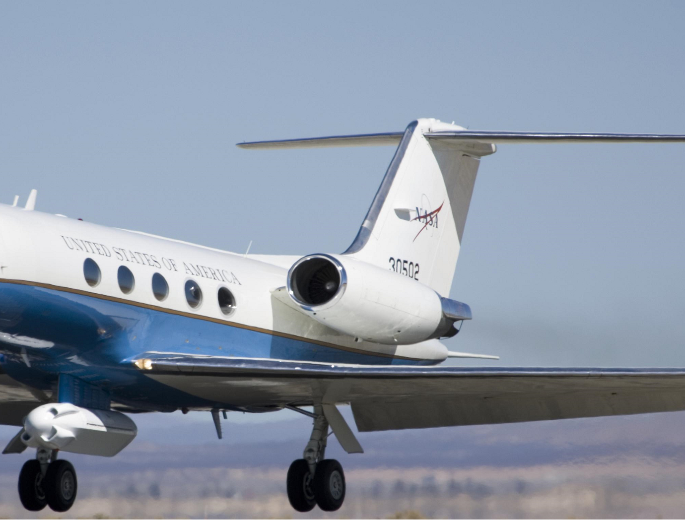
This technology is a new type of aircraft pylon design for noise control. A pylon connects the engine to the airframe of an aircraft. This design uses air passing through the pylon to actively disrupt the jet engine exhaust stream after it exits the engine, disrupting and redistributing the axial and azimuthal distributed sources of jet noise from the aircraft.
The Technology
For use on aircraft, the air intake would be on the pylon at an aerodynamically advantageous location. The delivery system would consist of pipes, a pump or pressure regulator and a plenum chamber. The air is piped through the internal pylon structure in pipes by a pump and to the plenum chamber. The injection site for the most common embodiments would be the shelf of the pylon (adjacent to the core nozzle flow) and the trailing edge of the pylon. The objective of the injection is to alter the trajectory of the core nozzle flow thereby impacting how the core and fan streams mix and the overall trajectory of the core and fan streams together. The injection site on the trailing edge has the objective of minimizing the wake of the pylon by injecting higher pressure and velocity air through the active aircraft pylon trailing edge injector. At cruise conditions, injection from the pylon trailing edge can also reduce the drag contribution of the pylon to the total aircraft drag.

Benefits
- Can be retrofit into existing aircraft pylon designs
- Reduces noise where jet exhaust interacts with control surfaces (flaps, ailerons, etc.)
- Redistributes noise sources within jet exhaust to enhance shielding of jet noise by the airframe surface (when applied to aircraft with engines above wings or fuselage such as on a Hybrid Wing Body)
Applications
- Commercial aircraft
- Business jets
- UAVs
Similar Results

Application of Leading Edge Serration and Trailing Edge Foam for Undercarriage Wheel Cavity Noise Reduction
Among the tests, landing gear cavities, a known cause of airframe noise, were evaluated. These are the regions where the landing gear deploys from the main body of an aircraft, typically leaving a large cavity where airflow can get pulled in, creating noise. NASA applied two concepts to these sections, including a series of chevrons placed near the front of the cavity with a sound-absorbing foam at the trailing wall, as well as a net that stretched across the opening of the main landing gear cavity. This altered the airflow and reduced the noise resulting from the interactions between the air, the cavity walls, and its edges.

Propeller/Rotor Phase Control for Reduction of Community Noise from Distributed Propulsion Vehicles
This innovation comprises a method of adjusting the relative angular positions of the propeller and/or rotor blades from a distributed propulsion system to favorably modify the spatial distribution of noise emanated by the vehicle, that is, the directivity pattern, for the purpose of reducing community noise. Adjusting these angular positions shows a great ability to act as a noise-canceling technique by way of destructive wave interference. Effectively, the acoustic energy can be steered away from noise-sensitive areas, e.g., schools, communities, etc. In the initial implementation, the phase angles can be calculated prior to flight. These depend on the propeller/rotor rotation rate, observer location, and relative propeller/rotor spacing, the latter being constant for a given vehicle. Optimization techniques determine the set of phase angles over the parametric space.

A New Twist Makes Rotating Machinery More Efficient and Quieter
Derived from a design approach for a new wing known as PRANDTL-D, this technology achieves similar improvements for propellers and other rotating machinery.
How It Works
To achieve the innovation's alternate spanload, Armstrong designers applied a non-linear twist to the propeller blade. The twist moves the load inward and dissipates the tip vortex over a wider area, minimizing its effect on drag. It also results in a decrease in load at the tip and reduced torque at the tip. These changes combine to achieve a dramatic reduction in power consumption without compromising the blade's other parameters. Specifically, the blade's diameter and rpm remain unchanged.
What Makes It Better
Unlike the conventional minimum induced loss (elliptical) spanload, which consumes large amounts of power at the tip of the blade, the new design unloads the tip and reduces torque, achieving significant improvements in efficiency. First-order analysis shows a more than 15 percent improvement in power consumption while producing the same thrust. The design also produces significantly less noise than conventional blade designs.

External Aircraft Noise Reduction Liners
This technology is an evolution of acoustic liners developed for engine noise abatement that are typically located inside nacelles. The acoustic liners described here can be outfitted on external surfaces and in tight spaces. Three initial areas of the aircraft have been considered as part of an aircraft configuration incorporating an open rotor propulsion system. The three areas where the liner configurations were applied were (1) under the rotor, (2) on the upper surface of the elevon, and (3) on the surface of a strut.

Multirotor Aircraft Noise Reduction
Noise produced by multirotor vehicles may be objectionable to some, especially as industry moves toward drone deliveries and potentially air taxi operations.
However, noise reductions can now be attained by synchronizing the rotation rate and then controlling the phase offset between neighboring rotors. The optimal phase offset is uniquely defined based on the number of blades and the relative location of each rotor and does not depend on the rotation rate, blade geometry, or other aspects of the vehicle design.
This technology is not viable for all multirotor aircraft but is applicable if the rotation rate of neighboring rotors can be synchronized mechanically or electronically.


