Methods for Predicting Transonic Flutter Using Simple Data Models
aerospace
Methods for Predicting Transonic Flutter Using Simple Data Models (TOP2-313)
Resolving Pitching Airfoil Transonic Aerodynamics by Computational Fluid Dynamics (CFD) Data Modeling
Overview
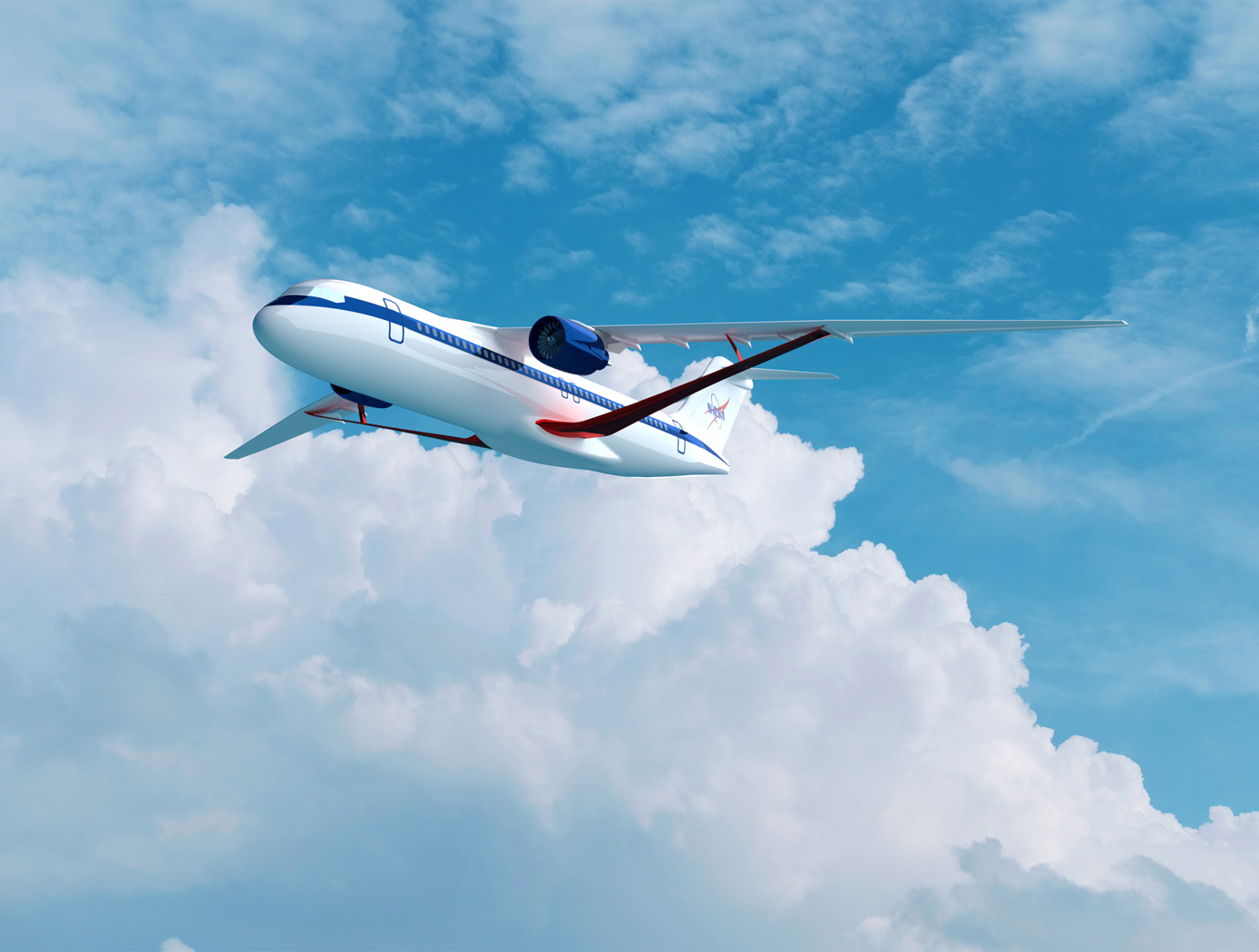
Aircraft moving at transonic speeds (i.e., ~0.7 to 0.85 Mach - or near the speed of sound) experience transonic wing flutter. Engineers have traditionally relied on experimental or computational methods to understand wing flutter for the design process. Modeling wing flutter using the customary computational methods require tens of hours of simulations on a supercomputer that are costly to buy or rent. Having a method to model wing flutter aerodynamics without requiring supercomputer use would (a) increase the efficiency and decrease the cost of aircraft wing design and (b) enable real-time wing-flutter modeling to aid in-flight aircraft operation and control. Ames Research Center has developed a novel closed-form solution to model wing flutter aerodynamics for any aircraft wing (within a certain thickness regime and without camber). This closed-form solution can be readily extended to wing sections with camber. The closed-form solution matches, in near real-time, the complex supercomputer simulations at a fraction of cost and time necessary to perform transonic flutter modeling for an airfoil.
The Technology
Transonic flutter is a pacing item in transport aircraft design in that it is crucial to characterize this phenomenon for each aircraft to prevent catastrophic failure. Aerodynamic study of flows around airfoils is a canonical problem that entails both experimental and computational approaches. While the transonic flutter prediction can be more accurate with high-fidelity Computational Fluid Dynamics (CFD) methods than with unsteady potential flow methods, the computational cost is high. Therefore, computationally efficient methods for transonic flutter prediction continue to be of high interest to the aircraft design community. NASA Ames has developed a novel method that eliminates the need for expensive calculations of aerodynamics of wing flutter, which typically takes tens of hours on a supercomputer. Such calculations are now replaced by machine-learning-based closed form solutions that provide the solution almost instantaneously. The technology presents a new approach to predict the flow around pitching NACA00 series airfoils. NACA airfoils are generally symmetric, and thus they do not possess camber. However, the invention can readily extend to wings with camber. This novel data modeling approach is orders of magnitude faster than the traditional CFD approach of predicting aerodynamic effects of transonic pitching airfoils. The data model is based on a subset of unsteady CFD simulations that train the model. The trained model then resolves the pitching airfoil in time for any other set on the order of a second, as compared with a complete CFD simulation that typically takes 30 hours on a supercomputer. The data model is demonstrated in this invention for transonic flow corresponding to Mach number of 0.755 over pitching NACA00 series airfoils for a reduced frequency range typical of flutter, i.e., k lies in the range 0.02 - 0.25.
 k=0.02, (b) k=0.05, (c) k=0.1, (d) k=0.15, (e) k=0.2, and (f) k=0.25")
Benefits
- Decreases cost and complexity of wing design: eliminates the need for supercomputer modeling (which can cost tens of thousands of dollars per simulation)
- Enables real-time flight control: simplified, computationally efficient method of modeling wing flutter aerodynamics offers near real-time opportunities to let computations influence in-flight aircraft control
- Applies to existing and future aircraft: enables the implementation of active wing control systems to manage flutter on existing aircraft
- Applies to wing sections (airfoils) that are symmetric or cambered
- Less expensive and more efficient method to design an airfoil while taking flutter into account (method is based on a closed-form solution)
- Can be applied to aircraft in any Mach regime
Applications
- Aircraft wing design
- Active aircraft wing control
- Rotorcraft blades as they have similar characteristics to wings
- Can be applied directly to linear viscoelastic materials undergoing cyclic sinusoidal forces
Technology Details
aerospace
TOP2-313
ARC-18593-1
Patent Pending
https://doi.org/10.1115/1.4050800
|
Tags:
|
|
|
Related Links:
|
Similar Results

Improved Fixed-Wing Gust Load Alleviation Device
Gust loads may have detrimental impacts on flight including increased structural and aerodynamic loads, structural deformation, and decreased flight dynamic performance. This technology has been demonstrated to improve current gust load alleviation by use of a trailing-edge, free-floating surface control with a mass balance. Immediately upon impact, the inertial response of the mass balance shifts the center of gravity in front of the hinge line to develop an opposing aerodynamic force alleviating the load felt by the wing. This passive gust alleviation control covering 33% of the span of a cantilever wing was tested in NASA Langleys low speed wind tunnel and found to reduce wing response by 30%.
While ongoing experimental work with new laser sensing technologies is predicted to similarly reduce gust load, simplicity of design of the present invention may be advantageous for certification processes. Additionally, this passive technology may provide further gust alleviation upon extending the use of the control to the entire trailing edge of the wing or upon incorporation with current active gust alleviation systems.
Importantly, the technology can be easily incorporated into to the build of nearly all fixed wing aircrafts and pilot control can be maintained through a secondary trim tab. Though challenging to retrofit, passive gust alleviation could enable use of thinner, more efficient wings in new plane design.

Real-Time Drag Opti-mization Control Framework
According to the International Air Transport Association statistics, the annual fuel cost for the global airline industry is estimated to be about $140 billion in 2017. Therefore, fuel cost is a major cost driver for the airline industry. Advanced future transport aircraft will likely employ adaptive wing technologies that enable the wings of those aircraft to adaptively reconfigure themselves in optimal shapes for improved aerodynamic efficiency throughout the flight envelope. The need for adaptive wing technologies is driven by the cost of fuel consumption in commercial aviation. NASA Ames has developed a novel way to address aerodynamic inefficiencies experienced during aircraft operation. The real-time drag optimization control method uses an on-board, real-time sensor data gathered from the aircraft conditions and performance during flight (such as engine thrust or wing deflection). The sensor data are inputted into an on-board model estimation and drag optimization system which estimates the aerodynamic model and calculates the optimal settings of the flight control surfaces. As the wings deflect during flight, this technology uses an iterative approach whereby the system continuously updates the optimal solution for the flight control surfaces and iteratively optimizes the wing shape to reduce drag continuously during flight. The new control system for the flight control surfaces can be integrated into an existing flight control system. This new technology can be used on passenger aircraft, cargo aircraft, or high performance supersonic jets to optimize drag, improve aerodynamic efficiency, and increase fuel efficiency during flight. In addition, it does not require a specific aircraft math model which means it does not require customization for different aircraft designs. The system promises both economic and environmental benefits to the aviation industry as less fuel is burned.

Supersonic Laminar Flow Control
This technique injects precisely defined stationary transient growth disturbances into the free air slipstream over a wing that develop into streamwise elongated "streaks." These streaks are created with an alternating pattern of low and high streamwise velocity in the boundary layer flow adjacent to the aerodynamic surface of interest. Judicious selection of streak wavelength, amplitude, and profile allows the first-mode instability waves responsible for transition via oblique mode breakdown to be damped while the remaining, uncontrolled waves are kept below an amplification threshold. A similar control concept is also applicable to second mode transition at hypersonic Mach numbers.

Multistage Free-Flight Testing System
The disclosed technology provides a multistage system for evaluating the free-flight behavior of test articles across of the supersonic, transonic, and subsonic regimes. First, a drop platform is lifted to high altitudes using a lifting device, such as a stratospheric balloon. The drop platform houses multiple projectiles, each containing an ejection mechanism, an on-board avionics suit, and an instrumented test article. Upon reaching the target altitude via the lifting device, the drop platform releases the projectiles sequentially. Each projectile accelerates to a target speed and altitude before ejecting its test article into the freestream. The test articles, such as a scaled re-entry capsule, then collect flight data during their descent through the various Mach regimes, providing valuable insights into their flight performance under mission-relevant conditions.
This innovative testing system offers several benefits. It enables the simultaneous testing of multiple vehicles, facilitating the evaluation of design variations as well as statistical analyses of vehicle behavior. This system also provides significant cost savings in comparison to other state-of-the-art testing methods, such as ballistic range testing. Additionally, the test articles within each projectile are easily interchangeable through a simple, modular change of a support surface in the ejection mechanism. This flexibility enables the system to accommodate a range of other aerodynamic technologies, including other vehicles, parachutes, propulsion systems, and defense technologies. This system can enhance the efficiency and robustness of reentry vehicle design, testing, and simulation operations through the collection of rich, flight-relevant data.

Calculation of Unsteady Aerodynamic Loads Using Fast-Response Pressure-Sensitive Paint (PSP)
Traditionally, unsteady pressure transducers have been the instrumentation of choice for investigating unsteady flow phenomena which can be time-consuming and expensive. The ability to measure and compute these flows has been a long-term challenge for aerospace vehicle designers and manufacturers. Results using only the pressure transducers are prone to inaccuracies, providing overly conservative load predictions in some cases and underestimating load predictions in other areas depending on the flow characteristics. NASA Ames has developed a new state-of-the-art method for measuring fluctuating aerodynamic-induced pressures on wind tunnel models using unsteady Pressure Sensitive Paint (uPSP). The technology couples recent advances in high-speed cameras, high-powered energy sources, and fast response pressure-sensitive paint. The unsteady pressure-sensitive paint (uPSP) technique has emerged as a powerful tool to measure flow, enabling time-resolved measurements of unsteady pressure fluctuations within a dense grid of spatial points on a wind tunnel model. The invention includes details surrounding uPSP processing. This technique enables time-resolved measurements of unsteady pressure fluctuations within a dense grid of spatial points representing the wind tunnel model. Since uPSP is applied by a spray gun, it is continuously distributed. With this approach, if the model geometry can be painted, viewed from a camera, and excited by a lamp source, uPSP data can be collected. Unsteady PSP (uPSP) has the ability to determine more accurate integrated unsteady loads.

