Search
Information Technology and Software
Additive Manufacturing Model-based Process Metrics (AM-PM)
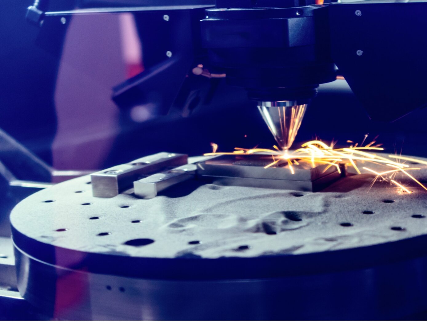
Modeling additive manufacturing processes can be difficult due to the scale difference between the active processing point (e.g., a sub-millimeter melt pool) and the part itself. Typically, the tools used to model these processes are either too computationally intensive (due to high physical fidelity or inefficient computations) or are focused solely on either the microscale (e.g., microstructure) or macroscale (e.g., cracks). These pitfalls make the tools unsuitable for fast and efficient evaluations of additive manufacturing build files and parts.
Failures in parts made by laser powder bed fusion (L-PBF) often come when there is a lack of fusion or overheating of the metal powder that causes areas of high porosity. AM-PM uses a point field-based method to model L-PBF process conditions from either the build instructions (pre-build) or in situ measurements (during the build). The AM-PM modeling technique has been tested in several builds including a Ti-6Al-4V test article that was divided into 16 parts, each with different build conditions. With AM-PM, calculations are performed faster than similar methods and the technique can be generalized to other additive manufacturing processes.
The AM-PM method is at technology readiness level (TRL) 6 (system/subsystem model or prototype demonstration in a relevant environment) and is available for patent licensing.
Sensors

Self-Calibrating Virtual Sensor
The virtual air data sensor leverages smartphone-grade inertial and GPS sensors with advanced computational methods to generate accurate air flow data in real time. The innovation uses inexpensive sensors typically present on smartphones, along with real-time modeling, filtering, and data reconstruction using kinematic equations. Operating within the aircraft fuselage, the algorithm avoids environmental exposure and flow field complications affecting traditional external sensors.
The algorithm employs a dual-methodology approach for real-time air flow estimation. It calibrates an aerodynamic model during calm air conditions, using aircraft response characteristics to compute air flow angles from vertical and lateral acceleration data through frequency-domain modeling. Simultaneously, kinematic relationships with GPS-corrected sensor bias estimation reconstruct independent air flow data at lower update rates. Advanced complementary filtering blends these streams to generate continuous airspeed, angle of attack, and sideslip angle measurements. The algorithm incorporates automated calibration, vertical acceleration-based alpha estimation, and GPS-based low-frequency angle reconstruction using kinematic expressions.
The innovative algorithm is self-calibrating and provides independent, reliable, and accurate virtual sensing that can be implemented with readily-available hardware. The technology is currently TRL 5 (component validated in relevant environment) and available for licensing.
Information Technology and Software

Lightning-AI: Predicting Lightning Occurrence Before Lightning Strikes
Lightning-AI is a machine learning system that addresses the critical gap in lightning safety by providing predictive warnings before the first strike occurs. The technology uses a combined CNN/LSTM architecture to identify atmospheric signals that lead to lightning initiation and converts them into short-term probabilistic forecasts. The model ingests four sequential WSR-88D radar scans spaced roughly 5 to 6 minutes apart, incorporating polarimetric variables including horizontal reflectivity, differential reflectivity, and correlation coefficient that reveal mixed-phase microphysics and graupel growth driving cloud electrification. The radar data is transformed into a uniform two-kilometer grid creating a consistent spatial framework. Before processing, data is normalized and filtered to remove non-meteorological clutter.
The model uses lightning initiation points from the Geostationary Lightning Mapper as ground truth observations to learn physical signatures of developing storms that appear minutes before the first flash. The CNN identifies spatial electrification patterns while the LSTM interprets their temporal evolution across sequential scans. Together, they detect subtle microphysical cues of impending lightning initiation, even before precipitation reaches the surface. This capability transforms lightning safety from reactive to proactive, offering more accurate threat identification. Validation results demonstrate the system can forecast lightning 15 to 30 minutes in advance, achieving an 84% probability of detection with a 22% false alarm rate. The algorithm operates in near-real-time using existing radar infrastructure and can integrate into commercial weather applications, emergency management systems, and automated alert platforms. Currently at TRL 5, Lightning-AI is available for patent licensing.
propulsion

HYPERFIRE
In order to maintain the low cost, simplicity, and quick turnaround of cold-flow testing while improving accuracy, NASA evaluated unconventional gases for use as simulants. During such evaluations, NASA discovered that by adjusting stagnation temperature, the isentropic exponent of ethane can be tuned to approximate those of common rocket propellants (e.g., hydrogen, hypergols, alcohols, and hydrocarbons). Furthermore, due to ethanes high auto-ignition temperature and resistance to condensation, tuned ethane enables testing of expansion ratios much larger than conventional inert-gas testing.
To leverage this discovery, NASA developed a hardware-based system to treat ethane and obtain nozzle chamber conditions that match the appropriate aerodynamics for a specific test. The system, named HYPERFIRE, works in the following manner. Liquid ethane is transferred to a piston-style run tank, where it is pressurized. Then, the ethane is run through two insulated pebble beds where it is heated, vaporized, and stabilized. Finally, the treated ethane is transferred from the second pebble bed to a small thrust takeout structure, and through the test article. Control of valves and regulators is managed by an onboard computer, accessed via a LabVIEW™ interface. The system is mounted on a hurricane-resistant steel frame to enable transportation via forklift.
Heated ethane reproduces the aerodynamics of combustion products at low temperatures relative to alternative testing methods. Thus, test articles can be manufactured using low-cost, low temperature rated, transparent materials (e.g., acrylic). In addition to reducing testing cost, this grants optical access to internal flowfields, enabling advanced diagnostic techniques (e.g., Schlieren imaging, particle image velocimetry) not possible with hot-fire testing and less meaningful with conventional cold-flow testing.
aerospace

Methods for Predicting Transonic Flutter Using Simple Data Models
Transonic flutter is a pacing item in transport aircraft design in that it is crucial to characterize this phenomenon for each aircraft to prevent catastrophic failure. Aerodynamic study of flows around airfoils is a canonical problem that entails both experimental and computational approaches. While the transonic flutter prediction can be more accurate with high-fidelity Computational Fluid Dynamics (CFD) methods than with unsteady potential flow methods, the computational cost is high. Therefore, computationally efficient methods for transonic flutter prediction continue to be of high interest to the aircraft design community. NASA Ames has developed a novel method that eliminates the need for expensive calculations of aerodynamics of wing flutter, which typically takes tens of hours on a supercomputer. Such calculations are now replaced by machine-learning-based closed form solutions that provide the solution almost instantaneously. The technology presents a new approach to predict the flow around pitching NACA00 series airfoils. NACA airfoils are generally symmetric, and thus they do not possess camber. However, the invention can readily extend to wings with camber. This novel data modeling approach is orders of magnitude faster than the traditional CFD approach of predicting aerodynamic effects of transonic pitching airfoils. The data model is based on a subset of unsteady CFD simulations that train the model. The trained model then resolves the pitching airfoil in time for any other set on the order of a second, as compared with a complete CFD simulation that typically takes 30 hours on a supercomputer. The data model is demonstrated in this invention for transonic flow corresponding to Mach number of 0.755 over pitching NACA00 series airfoils for a reduced frequency range typical of flutter, i.e., k lies in the range 0.02 - 0.25.
Mechanical and Fluid Systems
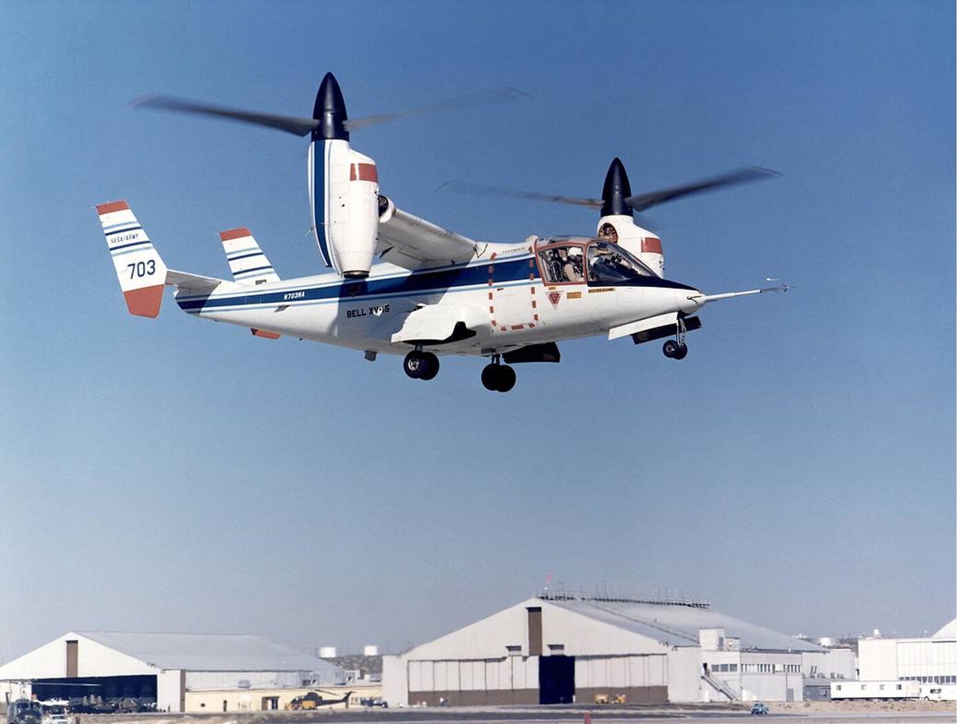
Improving VTOL Proprotor Stability
Proprotors on tiltrotor aircraft have complex aeroelastic properties, experiencing torsion, bending, and chord movement vibrational modes, in addition to whirl flutter dynamic instabilities. These dynamics can be stabilized by high-frequency swashplate adjustments to alter the incidence angle between the swashplate and the rotor shaft (cyclic control) and blade pitch (collective control). To make these high-speed adjustments while minimizing control inputs, generalized predictive control (GPC) algorithms predict future outputs based on previous system behavior. However, these algorithms are limited by the fact that tiltrotor systems can substantially change in orientation and airspeed during a normal flight regime, breaking system continuity for predictive modeling.
NASA’s Advanced GPC (AGPC) is a self-adaptive algorithm that overcomes these limitations by identifying system changes and adapting its predictive behavior as flight conditions change. If system vibration conditions deteriorate below a set threshold for a set time interval, the AGPC will incrementally update its model parameters to improve damping response. AGPC has shown significant performance enhancements over conventional GPC algorithms in comparative simulations based on an analytical model of NASA’s TiltRotor Aeroelastic Stability Testbed (TRAST). Research for Hardware-In-the-Loop testing and flight vehicle deployment is ongoing, and hover data show improved vibration reduction and stability performance using AGPC over other methods.
The example presented here is an application to tiltrotor aircraft for envelope expansion and vibration reduction. However, AGPC can be employed on many dynamic systems.

