Search
PATENT PORTFOLIO
Aerospace
NASA has a wide range of advanced aerospace technologies that can be useful for both small companies seeking to introduce new solutions and large corporations looking to improve their capabilities. These technologies have the potential to transform the aerospace industry and drive the development of innovative solutions.
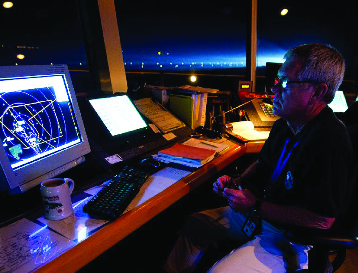
FACET: Future Air Traffic Management Concepts Evaluation Tool
Actual air traffic data and weather information are utilized to evaluate an aircrafts flight-plan route and predict its trajectories for the climb, cruise, and descent phases. The dynamics for heading (the direction the aircraft nose is pointing) and airspeed are also modeled by the FACET software, while performance parameters, such as climb/descent rates and speeds and cruise speeds, can also be obtained from data tables. The resulting trajectories and traffic flow data are presented in a 3-D graphical user interface. The FACET software is modular and is written in the Java and C programming languages. Notable FACET applications include reroute conformance monitoring algorithms that have been implemented in one of the Federal Aviation Administrations nationally deployed, real-time operational systems.
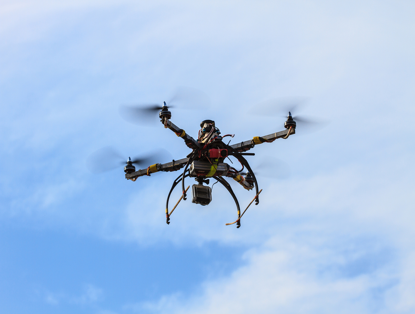
Unmanned Aerial Systems (UAS) Traffic Management
NASA Ames has developed an Autonomous Situational Awareness Platform system for a UAS (ASAP-U), a traffic management system to incorporate Unmanned Aerial Systems (UASs) into the National Airspace System. The Autonomous Situational Awareness Platform (ASAP) is a system that combines existing navigation technology (both aviation and maritime) with new procedures to safely integrate Unmanned Aerial Systems (UASs) with other airspace vehicles. It uses a module called ASAP-U, which includes a transmitter, receivers, and various links to other UAS systems. The module collects global positioning system GPS coordinates and time from a satellite antenna, and this data is fed to the UAS's flight management system for navigation. The ASAP-U module autonomously and continuously sends UAS information via a radio frequency (RF) antenna using Self-Organized Time Division Multiple Access (SOTDMA) to prevent signal overlap. It also receives ASAP data from other aircraft. In case of transmission overload, priority is given to closer aircraft. Additionally, the module can receive weather data, navigational aid data, terrain data, and updates to the UAS flight plan. The collected data is relayed to the flight management system, which includes various databases and a navigation computer to calculate necessary flight plan modifications based on regulations, right-of-way rules, terrain, and geofencing. Conflicts are checked against databases, and if none are found, the flight plan is implemented. If conflicts arise, modifications can be made. The ASAP-U module continuously receives and transmits data, including UAS data and data from other aircraft, to detect conflicts with other aircraft, terrain, weather, and geofencing. Based on this information, the flight management system determines the need for course adjustments and the flight control system executes them for a safe flight route.

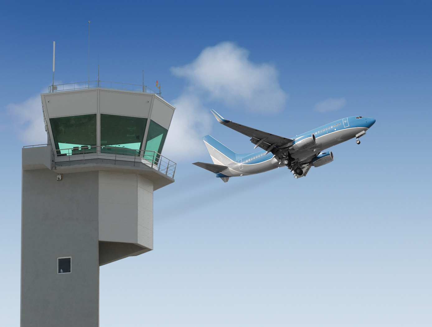
Vision-based Approach and Landing System (VALS)
The novel Vision-based Approach and Landing System (VALS) provides Advanced Air Mobility (AAM) aircraft with an Alternative Position, Navigation, and Timing (APNT) solution for approach and landing without relying on GPS. VALS operates on multiple images obtained by the aircraft’s video camera as the aircraft performs its descent. In this system, a feature detection technique such as Hough circles and Harris corner detection is used to detect which portions of the image may have landmark features. These image areas are compared with a stored list of known landmarks to determine which features correspond to the known landmarks. The world coordinates of the best matched image landmarks are inputted into a Coplanar Pose from Orthography and Scaling with Iterations (COPOSIT) module to estimate the camera position relative to the landmark points, which yields an estimate of the position and orientation of the aircraft. The estimated aircraft position and orientation are fed into an extended Kalman filter to further refine the estimation of aircraft position, velocity, and orientation. Thus, the aircraft’s position, velocity, and orientation are determined without the use of GPS data or signals. Future work includes feeding the vision-based navigation data into the aircraft’s flight control system to facilitate aircraft landing.

Multistage Free-Flight Testing System
The disclosed technology provides a multistage system for evaluating the free-flight behavior of test articles across of the supersonic, transonic, and subsonic regimes. First, a drop platform is lifted to high altitudes using a lifting device, such as a stratospheric balloon. The drop platform houses multiple projectiles, each containing an ejection mechanism, an on-board avionics suit, and an instrumented test article. Upon reaching the target altitude via the lifting device, the drop platform releases the projectiles sequentially. Each projectile accelerates to a target speed and altitude before ejecting its test article into the freestream. The test articles, such as a scaled re-entry capsule, then collect flight data during their descent through the various Mach regimes, providing valuable insights into their flight performance under mission-relevant conditions.
This innovative testing system offers several benefits. It enables the simultaneous testing of multiple vehicles, facilitating the evaluation of design variations as well as statistical analyses of vehicle behavior. This system also provides significant cost savings in comparison to other state-of-the-art testing methods, such as ballistic range testing. Additionally, the test articles within each projectile are easily interchangeable through a simple, modular change of a support surface in the ejection mechanism. This flexibility enables the system to accommodate a range of other aerodynamic technologies, including other vehicles, parachutes, propulsion systems, and defense technologies. This system can enhance the efficiency and robustness of reentry vehicle design, testing, and simulation operations through the collection of rich, flight-relevant data.

Affordable Vehicle Avionics (AVA)
Significant contributors to the cost of launching nano- and micro-satellites to orbit are the costs of software, and Guidance, Navigation and Control (GNC) avionics systems that steer, navigate and control the launch vehicles, sequence stage separation, deploy payloads, and pass data to Telemetry. The high costs of these GNC avionics systems are due in part to the current practice of developing unique, custom, single-use hardware and software for each launch, and requiring high-precision measurements of position and attitude states. NASA Ames Research Center has developed and tested a low-cost avionics system prototype called Affordable Vehicle Avionics (AVA). AVA integrates a low-cost moderately-precise sensor suite with an advanced error-correcting software package to provide GNC for space launch vehicles in a package smaller than a multilayer sandwich (100 mm x 120 mm x 69 mm; 4in x 4.7in x 2.7in), and with a mass of less than 0.84kg (2lbs). The invention provides a common suite of avionics components and demonstration software that deliver affordable, capable GNC with flexible I/O which is applicable to a variety of nano/micro-sat launch vehicles at less than 10 percent of the cost to procure current state-of-the-art GNC avionics. Affordable Vehicle Avionics' (AVA's) approach to drastically reduce costs includes: (1) use of low-cost "tactical-grade" Commercial-off-the-Shelf MicroElectroMechanical Systems (MEMS) inertial measurement unit, wherein adequate navigation precision is achieved by fusing outputs from a Global Positioning System receiver, inertial sensors and a magnetic field vector sensor in an extended Kalman filter formulation that corrects inertial sensor biases; (2) a streamlined "cookbook" approach to define an effective process for launch vehicle developers to design, simulate, verify and support assembly, integration and testing of their SLVs, driven by high-fidelity six degrees of freedom SLV simulations and real-time hardware-in-loop tests to validate guidance, navigation and control for early test flights.
Development Status:
As of spring 2020, AVA has flown twice in its current configuration on a suborbital platform. Its navigation and control functions were successfully demonstrated for roll-rate control within a tight deadband onboard the first flight test, and it successfully issued attitude pointing commands to a failed reaction control subsystem and it issues issued a rocket-motor ignition command on a second flight test. To date, failure of SLV components other than AVA (e.g., electrical power) has precluded demonstration of navigation and control of an orbital or sub-orbital launch system, which remains to be demonstrated.
AVA development was accomplished using a single magnetometer-based magnetic field vector sensor to provide attitude observability during free-fall (inter-stage coast periods). Therefore, the current tested AVA configuration is susceptible to magnetic/electric fields produced by other components and payloads onboard the SLV, so care must be exercised to either mount AVA well away from sources of such fields and or to incorporate magnetic/electric field barriers on field emitters if separation from emitters is inadequate. Also, licensees may wish to provide new AVA inputs from a pair of external horizon sensors to provide more accurate attitude navigation during coast phases of the SLV mission.
Method and System for Air Traffic Rerouting for Air-space Constraint Resolution
National Airspace System (NAS) Constraint Evaluation and Notification Tool (NASCENT) employs a NAS-wide simulation and analysis infrastructure that implements airspace constraint avoidance algorithms for efficient routing. NASCENT uses NASA-developed aircraft performance tables for computing climb, cruise, and descent trajectories. Reference routes are created that save more than a user-specified number (e.g., five) minutes of flying-time savings. The return capture fix for the reference route is the last fix on the current flight plan within a limit region (derived using this patented technology). A Maneuver Start Point is selected to allow time for coordination of the reroute with the Federal Aviation Administration (FAA). These routes are checked against the weather polygons, FAA denoted Special Use Airspaces (e.g., Military Operations Areas) and Temporary Flight Restrictions (TFRs); and additional waypoints are added to avoid these airspace constraints. The wind-corrected flying-time savings are reported for each flight. The polygons are first converted into convex hulls and inflated by a user-specified number of nautical miles (e.g., 20, for weather) to account for the FAA requirements. Lateral and/or vertical advisories are created using a binary tree search along the left-side and right-side, up to the return capture fix, to find a minimum-deviation delay solution. The NASCENT system provides notification for congested sectors along the current flight plan and the proposed avoidance route, along with flights impacted by FAA imposed required Traffic Management Initiatives (TMIs, reroutes, Ground Delay Programs, etc.). The reroutes can be implemented with no changes required to the current FAA operational infrastructure.
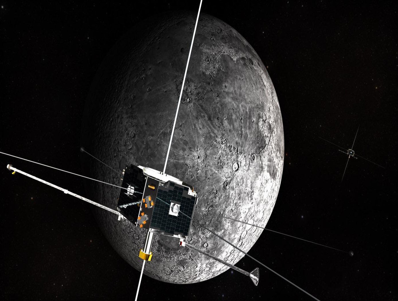
Method for Transferring a Spacecraft from Geosynchronous Transfer Orbit to Lunar Orbit
The invention presents a trajectory design whereby a spacecraft can be launched as a secondary payload into a Geosynchronous Transfer Orbit (GTO) and through a series of maneuvers to reach lunar orbit. The trajectory analysis begins by identifying acceptable ranges of lunar orbit altitude and inclination values. The unique features of this method includes the use of either a leading or trailing edge lunar flyby to achieve an orbit inclination in the lunar orbit plane from a GTO launched at any time of day. This technique is applicable to secondary spacecraft that share a ride to space resulting in a substantially reduced cost, and with no control of the launch conditions. Major advantages of this design include the relatively short (maximum) lunar transfer duration (<3 months, less than half of that required for a Sun-Earth weak-stability boundary transfer), simplicity and consistency of design (again compared to a Sun-Earth weak stability boundary transfer).

Flight Awareness Collaboration Tool (FACT)
The Flight Awareness Collaboration Tool (FACT) user interface is a quad design with four areas. The Primary Map View shows the US with several traffic and weather overlays. The Surface Map View displays the selected airport with information on runway conditions and other factors. The Information View has specific data from various sources about the area of interest. This view also has a built-in algorithm that predicts the impact of the forecast winter weather on airport capacity. The Communication View supports messaging within the geographically-dispersed team that is using FACT. When an airport is selected in the Primary Map View, the information presented in the Surface Map and Information Views is focused on that choice.
FACT is a web-based application using Node.js and MongoDB. It receives Java messages from the Federal Aviation Administration System Wide Information Management (SWIM) data repository. Data acquired from web pages and SWIM are tailored for FACTs Information View area. FACT is designed to reside on an existing workstation monitor to be put into use as needed.
Transformable Hypersonic Aerodynamic Decelerator
The invention allows the deployment of a large aerodynamic decelerator relative to the size of its launch vehicle, which is controllable and can be transformed into a landing system. A structure composed of a radial assembly of ribs and struts in a four bar linkage arrangement fits inside a launch vehicle shroud, expands into a deployed size, and permits rotation about a pivot point along the vehicle axis. The mechanism that deploys the decelerator surface, doubles as the actuation/control mechanism, and triples as the payload surface leveling system. The design permits the use of conformable thermal protection systems at the central part and a flexible TPS, 3-D woven carbon fabric, as skin in the majority of the regions of the aeroshell entry system. The fabric handles both the heat and mechanical load generated during entry. This system is very mass competitive with other lightweight systems such as inflatable and rigid decelerators and is believed to be more reliable and testable at sub-scale. Once the payload reaches its destination, the decelerator structure leverages atmospheric drag to slow the craft from hypersonic travel speeds to an appropriate landing velocity. The decelerator can be actuated during descent to generate lift and steer the payload to its intended destination. Retro propulsion engines provide the final deceleration just before landing, and the decelerator structure is inverted to act as a landing platform and help minimize the impact of landing load.
View more patents

