Search
PATENT PORTFOLIO
.jpg)
Interim, In Situ Additive Manufacturing Inspection
The in situ inspection technology for additive manufacturing combines different types of cameras strategically placed around the part to monitor its properties during construction. The IR cameras collect accurate temperature data to validate thermal math models, while the visual cameras obtain highly detailed data at the exact location of the laser to build accurate, as-built geometric models. Furthermore, certain adopted techniques (e.g., single to grouped pixels comparison to avoid bad/biased pixels) reduce false positive readings.
NASA has developed and tested prototypes in both laser-sintered plastic and metal processes. The technology detected errors due to stray powder sparking and material layer lifts. Furthermore, the technology has the potential to detect anomalies in the property profile that are caused by errors due to stress, power density issues, incomplete melting, voids, incomplete fill, and layer lift-up. Three-dimensional models of the printed parts were reconstructed using only the collected data, which demonstrates the success and potential of the technology to provide a deeper understanding of the laser-metal interactions. By monitoring the print, layer by layer, in real-time, users can pause the process and make corrections to the build as needed, reducing material, energy, and time wasted in nonconforming parts.

Ultrasonic Stir Welding
Ultrasonic Stir Welding is a solid state stir welding process, meaning that the weld work piece does not melt during the welding process. The process uses a stir rod to stir the plasticized abutting surfaces of two pieces of metallic alloy that forms the weld joint. Heating is done using a specially designed induction coil. The control system has the capability to pulse the high-power ultrasonic (HPU) energy of the stir rod on and off at different rates from 1-second pulses to 60-millisecond pulses. This pulsing capability allows the stir rod to act as a mechanical device (moving and stirring plasticized nugget material) when the HPU energy is off, and allowing the energized stir rod to transfer HPU energy into the weld nugget (to reduce forces, increase stir rod life, etc.) when the HPU energy is on. The process can be used to join high-melting-temperature alloys such as titanium, Inconel, and steel.
Sublimable Propellant Source for Iodine-fed Ion Propulsion System
NASAs iodine vapor feed system is based on a mechanism that holds and maintains the solid iodine is contact with a heated surface, in this case the walls of the propellant tank. The mechanism provides a robust and reliable steady-state delivery of sublimated iodine vapor to the ion propulsion system by ensuring good thermal contact between the solid iodine and the tank walls.
To date, the technology development effort includes extensive thermal, mechanical and flow modelling together with testing of components and subsystems required to feed iodine propellant to a 200-W Hall thruster. The feed system has been designed to use materials that are resistant to the highly-reactive nature of iodine propellant. Dynamic modeling indicates that the feed system tubing can be built is such a way as to reduce vibrationally-induced stresses that occur during launch. Thermal modeling has been performed to demonstrate that the feed system heater power levels are sufficient to heat the tank and propellant lines to operating temperatures, and sublime the iodine in the storage tank to supply propellant for reliable and long-term operation.
Tension Element Vibration Damping
NASAs Tension Element Vibration Damping technology presents a novel method of managing the dynamic behavior of structures by capturing the vibrational displacement of the structure via a connecting link and using this motion to drive a resistive element. The resistive element then provides a force feedback that manages the dynamic behavior of the total system or structure. The damping force feedback can be a tensile or compressive force, or both. Purely tensile force has advantages for packaging and connection alignment flexibility while combined tensile/compression forces have the advantage of providing damping over a complete vibratory cycle.
This innovation can be readily applied to existing structures and incorporated into any given design as the connecting element is easily affixed to displacing points within the structure and the resistive element to be located in available space or a convenient location. The resistive element can be supplied by any one of either hydraulic, pneumatic or magnetic forces. As such the innovation can provide a wide range of damping forces, a linear damping function and/or an extended dynamic range of attenuation, providing broad flexibility in configuration size and functional applicability.
NASA-built prototypes have been shown to be highly effective on a 170-foot long wind turbine blade in test beds at the University of Maine.
.jpg)
Tool for Rapid Identification of TCE in Plants
Plant uptake of TCE from contaminated groundwater is a well-known phenomenon. During the photosynthesis process, plants metabolize the TCE into a byproduct called trichloroacetic acid (TCAA). TCAA has been found to be a good indicator (or surrogate) molecule for the presence of TCE because it is more stable than TCE in plants. The hyperspectral estimator is being designed to detect TCAA. The method uses a white light that is directed at the surface of a plant's leaf. The interaction between the light and the leaf produces spectral signatures that are captured using a detector. A processor that will be coupled to the detector will compare these signatures to a library/database of signatures known to be indicators of the presence of TCAA (and thus TCE). The figure below on the left shows hyperspectral images captured using the method for leaves dosed with TCE over various time periods. These images are examples of response signatures that will eventually be built into the device's reference library/database. Proof-of-concept testing has shown that the hyperspectral estimator is capable of estimating the presence/absence of TCE in plant leaves with an accuracy of 80%. Efforts are now underway to further improve the accuracy of this method and to prototype the technology. The figure below on the right shows a diagram of the planned device.
Improving Formability of Al-Li Alloys
Via this NASA innovation, a product is first heated to a temperature within the range of 204 to 343 degrees C for an extended soak of up to 16 hours. The product is then slowly heated to a second temperature within the range of 371 to 482 degrees C for a second soak of up to 12 hours. Finally, the product is slowly cooled to a final soak temperature of 204 to 343 degrees C before cooling to room temperature. The product so treated will exhibit greatly improved formability.
To date, the low formability issue has limited the use of lightweight Al-Li alloys for large rocket fuel tank dome applications. Manufacturing a dome by stretch forming typically requires multiple panels as well as multiple welding and inspection steps to assemble these panels into a full-scale fuel tank dome. Complex tensile and bending stresses induced during the stretch forming operations of Al-Li alloys have resulted in high rates of failure for this process. To spin form a large rocket dome, the spin blank must be prepared by joining smaller plates together using friction stir welding. However, friction stir welding produces a distinct metallurgical structure inside and around the friction stir weld that makes it very susceptible to cracking during spin forming.
.jpg)
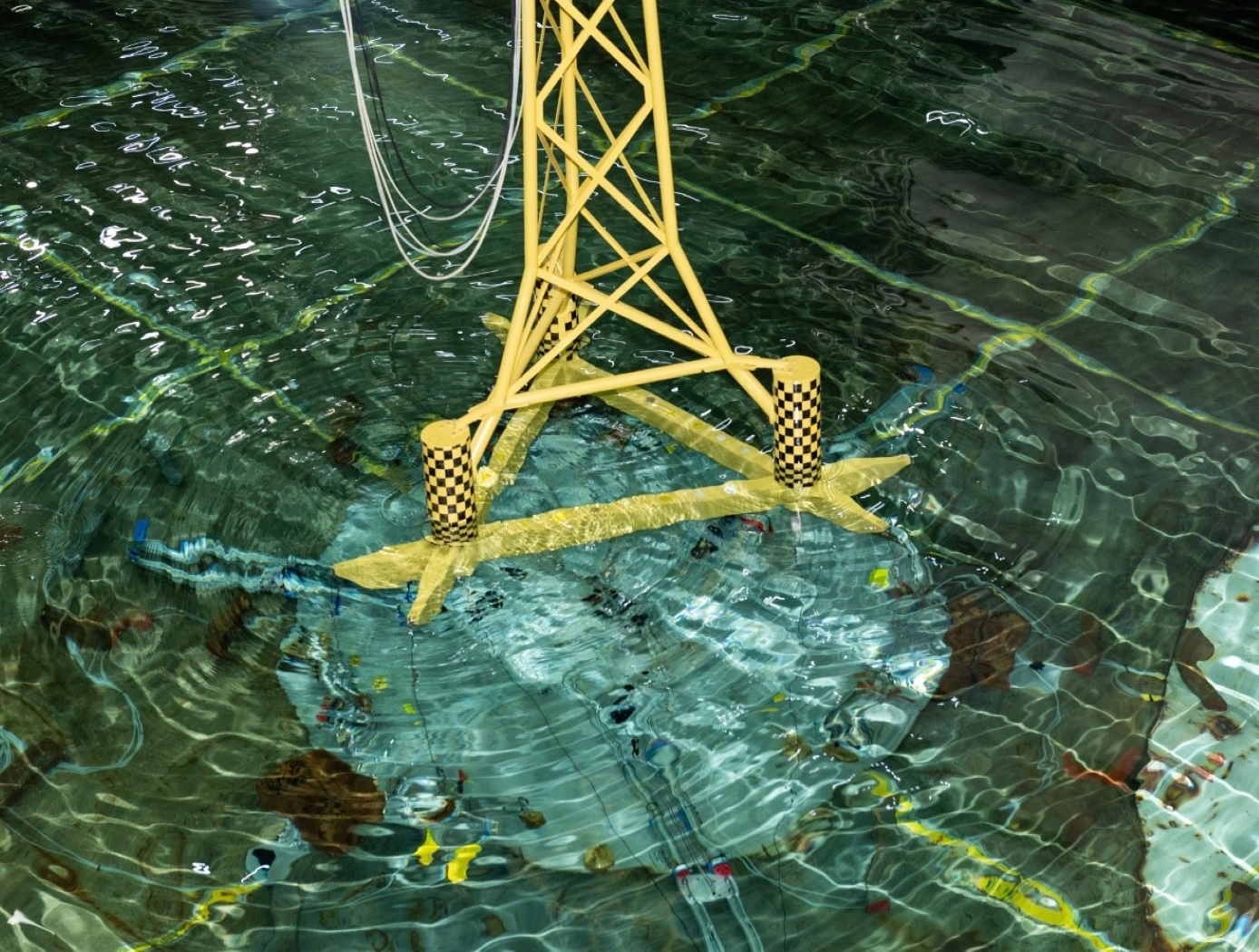
Fluid-Filled Frequency-Tunable Mass Damper
NASA MSFC’s Fluid-Filled Frequency-Tunable Mass Damper (FTMD) technology implements a fluid-based mitigation system where the working mass is all or a portion of the fluid mass that is contained within the geometric configuration of either a channel, pipe, tube, duct and/or similar type structure. A compressible mechanism attached at one end of the geometric configuration structure enables minor adjustments that can produce large effects on the frequency and/or response attributes of the mitigation system.
Existing fluid-based technologies like Tuned Liquid Dampers (TLD) and Tuned Liquid Column Dampers (TLCD) rely upon the geometry of a container to establish mitigation frequency and internal fluid loss mechanisms to set the fundamental mitigation attributes. The FTMD offers an innovative replacement since the frequency of mitigation and mitigation attributes are established by the compressible mechanism at the end of the container. This allows for simple alterations of the compressible mechanism to make frequency adjustments with relative ease and quickness.
FTMDs were recently successfully installed on a building in Brooklyn, NYC as a replacement for a metallic TMD, and on a semi-submersible marine-based wind turbine in Maine.
The FTMD technology is available for non-exclusive licensing and partially-exclusive licensing (outside of building construction over 300 feet).

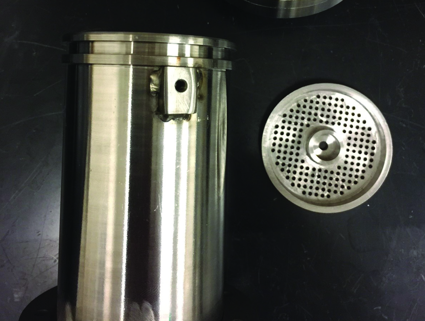
High Flow Differential Cleaning
NASA developed this High Flow Differential Cleaning technology in response to in-house needs for a more automated and effective method to remove stubborn particles from complex parts fabricated using powder-bed-fusion equipment. The invention uses a large volume of pressurized air to quickly enter a cleaning chamber. Based on the Bernoulli principle and Continuity equation, the high flow results in significant air velocity and a decrease in pressure when airflow passes through smaller component orifices, which in turn removes remnant powder from the part. In one embodiment, the invention consists of a (1) high-pressure air compressor with ISO 8573 Class 2 drying capability, (2) a large pressure chamber with a fast-actuated valve system to, (3) a cleaning chamber containing various sensors, injection systems, (4) a test fixture designed for easy orientation adjustments, and (5) an expansion chamber allowing air to expand and drop in velocity, particles to settle, and filtered air to re-enter the room. This NASA technology can be implemented as a standalone cleaning system for powder bed fusion additively manufactured parts, or could be integrated into a packaged post-processing system offering. CT scans of complex NASA parts cleaned using a proof-of-concept system based upon the invention revealed very promising results.
NASA welcomes industry to test the cleaning speed and efficacy of the technology under an evaluation license.

Internal Friction Reduction (IFR) Tool
During SR-FSW, the wicking of substrate material into the gap between the crown shoulder and pin can lead to pinch load shifting–an increasing difference between the applied pin load and actual pinch load. NASA's IFR Tool mitigates pinch load shifting, enabling a more robust SR-FSW process due to better agreement between the applied pin load and the actual pinch load.
As pinch loads are not dynamically measured during welding, NASA has relied on defect rates and pin tool ejection loads to demonstrate the value of the IFR Tool. Large-scale welds were performed with both the IFR Tool and a standard pin tool. Weld inspections found a 90% reduction in defect generation rate for the IFR tool, and the first defect in the standard pin tool sample occurred at 300" compared to at 900" in the IFR Tool sample. There was also a drastic improvement in mechanical properties variations along the weld.
In another study, a series of 27.5' barrel welds were performed with both the IFR Tool and a standard pin tool. After welding, ejection forces required to remove the pin tools from their fixtures were measured. The standard pin tool ejection force was 9,400 lbs., nearly 5 times larger than that of the IFR Tool at 2,000 lbs . The large difference suggests that during welding, the standard pin tool would have been less responsive to substrate surface variations than the IFR Tool. Weld inspections supported this theory, as they found a significantly lower defect rate in the IFR Tool samples.
View more patents

