Search
Aerospace

Real-Time Drag Opti-mization Control Framework
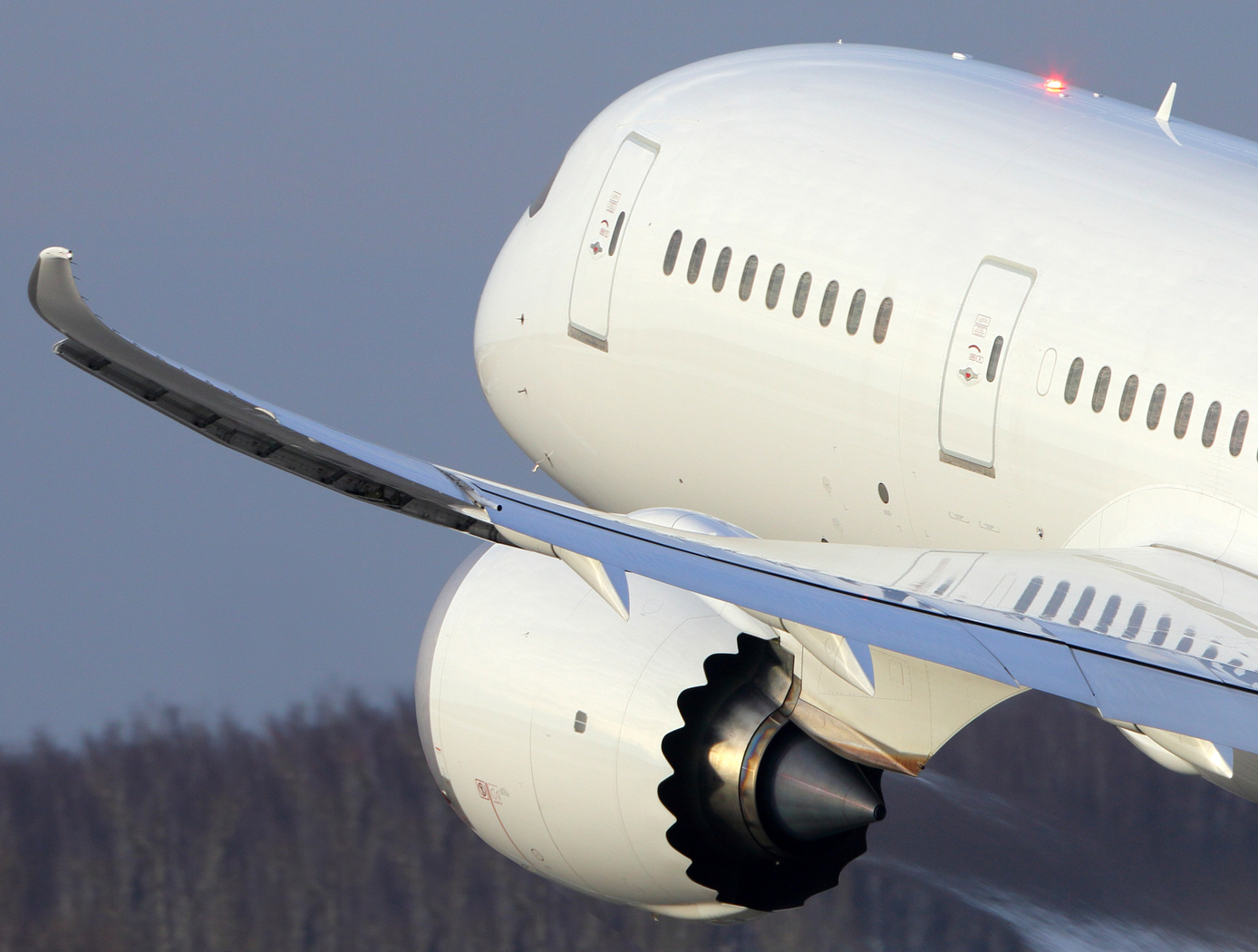
According to the International Air Transport Association statistics, the annual fuel cost for the global airline industry is estimated to be about $140 billion in 2017. Therefore, fuel cost is a major cost driver for the airline industry. Advanced future transport aircraft will likely employ adaptive wing technologies that enable the wings of those aircraft to adaptively reconfigure themselves in optimal shapes for improved aerodynamic efficiency throughout the flight envelope. The need for adaptive wing technologies is driven by the cost of fuel consumption in commercial aviation. NASA Ames has developed a novel way to address aerodynamic inefficiencies experienced during aircraft operation. The real-time drag optimization control method uses an on-board, real-time sensor data gathered from the aircraft conditions and performance during flight (such as engine thrust or wing deflection). The sensor data are inputted into an on-board model estimation and drag optimization system which estimates the aerodynamic model and calculates the optimal settings of the flight control surfaces. As the wings deflect during flight, this technology uses an iterative approach whereby the system continuously updates the optimal solution for the flight control surfaces and iteratively optimizes the wing shape to reduce drag continuously during flight. The new control system for the flight control surfaces can be integrated into an existing flight control system. This new technology can be used on passenger aircraft, cargo aircraft, or high performance supersonic jets to optimize drag, improve aerodynamic efficiency, and increase fuel efficiency during flight. In addition, it does not require a specific aircraft math model which means it does not require customization for different aircraft designs. The system promises both economic and environmental benefits to the aviation industry as less fuel is burned.
aerospace
Improved Fixed-Wing Gust Load Alleviation Device
Gust loads may have detrimental impacts on flight including increased structural and aerodynamic loads, structural deformation, and decreased flight dynamic performance. This technology has been demonstrated to improve current gust load alleviation by use of a trailing-edge, free-floating surface control with a mass balance. Immediately upon impact, the inertial response of the mass balance shifts the center of gravity in front of the hinge line to develop an opposing aerodynamic force alleviating the load felt by the wing. This passive gust alleviation control covering 33% of the span of a cantilever wing was tested in NASA Langleys low speed wind tunnel and found to reduce wing response by 30%.
While ongoing experimental work with new laser sensing technologies is predicted to similarly reduce gust load, simplicity of design of the present invention may be advantageous for certification processes. Additionally, this passive technology may provide further gust alleviation upon extending the use of the control to the entire trailing edge of the wing or upon incorporation with current active gust alleviation systems.
Importantly, the technology can be easily incorporated into to the build of nearly all fixed wing aircrafts and pilot control can be maintained through a secondary trim tab. Though challenging to retrofit, passive gust alleviation could enable use of thinner, more efficient wings in new plane design.
Aerospace

Multistage Free-Flight Testing System
The disclosed technology provides a multistage system for evaluating the free-flight behavior of test articles across of the supersonic, transonic, and subsonic regimes. First, a drop platform is lifted to high altitudes using a lifting device, such as a stratospheric balloon. The drop platform houses multiple projectiles, each containing an ejection mechanism, an on-board avionics suit, and an instrumented test article. Upon reaching the target altitude via the lifting device, the drop platform releases the projectiles sequentially. Each projectile accelerates to a target speed and altitude before ejecting its test article into the freestream. The test articles, such as a scaled re-entry capsule, then collect flight data during their descent through the various Mach regimes, providing valuable insights into their flight performance under mission-relevant conditions.
This innovative testing system offers several benefits. It enables the simultaneous testing of multiple vehicles, facilitating the evaluation of design variations as well as statistical analyses of vehicle behavior. This system also provides significant cost savings in comparison to other state-of-the-art testing methods, such as ballistic range testing. Additionally, the test articles within each projectile are easily interchangeable through a simple, modular change of a support surface in the ejection mechanism. This flexibility enables the system to accommodate a range of other aerodynamic technologies, including other vehicles, parachutes, propulsion systems, and defense technologies. This system can enhance the efficiency and robustness of reentry vehicle design, testing, and simulation operations through the collection of rich, flight-relevant data.
aerospace
Multi-Objective Flight Control Optimization Framework
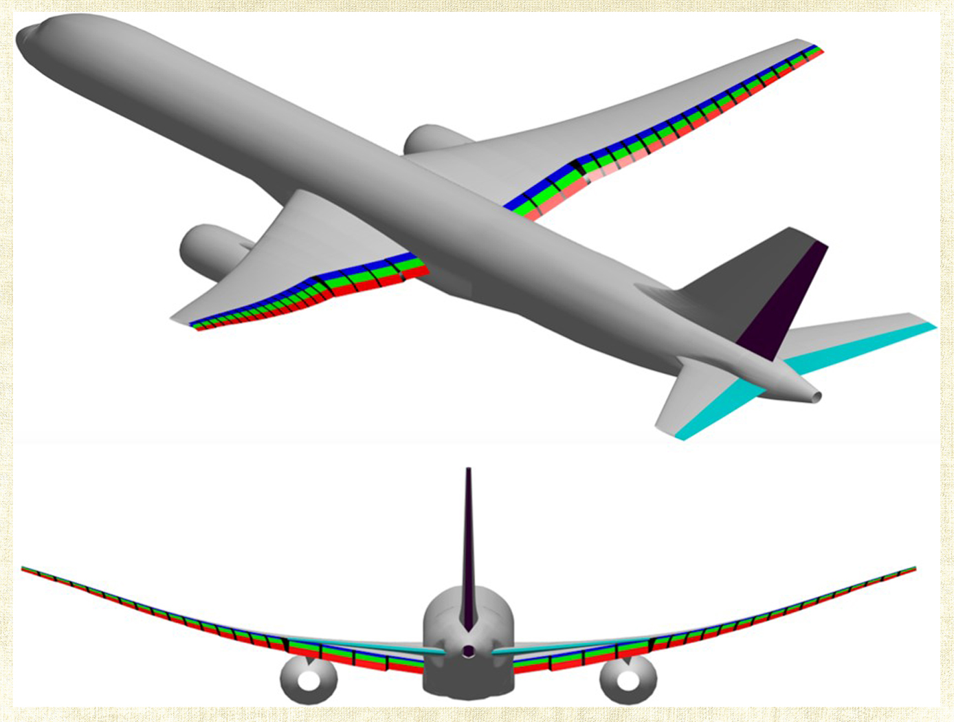
Composite materials are being used in aerospace design because of their high strength-to-weight ratio. On modern airplanes, composite wings offer a greater degree of aerodynamic efficiency due to weight savings, but at the same time introduce more structural flexibility than their aluminum counterparts. Under off-design flight conditions, changes in the wing shape due to structural flexibility cause the wing aerodynamics to be non-optimal. This effect could offset any weight saving benefits realized by the composite wings. Structural flexibility could also cause adverse interactions with flight control and structural vibration which can compromise aircraft stability, pilot handling qualities, and passenger ride quality. NASA Ames Research Center has developed a novel technology that employs a new multi-objective flight control optimization framework to achieve multiple control objectives simultaneously. This technology leverages the availability of distributed flight control surfaces in modern transports. The multi-objective flight control technology comprises the following objectives all acting in a synergistic manner: 1) traditional stability augmentation and pilot command-following flight control, 2) drag minimization, 3) aeroelastic mode suppression, 4) gust load alleviation, and 5) maneuver load alleviation. Each of these objectives can be a major control system design in its own right. Thus, the multi-objective flight control technology can effectively manage the complex interactions of the individual single-objective flight control system design and take into account multiple competing requirements to achieve optimal flight control solutions that have the best compromise for these requirements. In addition, a real- time drag minimization control strategy is included in the guidance loop. This feature utilizes system identification methods to estimate aerodynamic parameters for the on-line optimization. The aerodynamic parameters are also used in the multi-objective flight control for drag minimization and maneuver/ gust load alleviation control.
aerospace

Advanced Fire Detection for Aircraft Cargo Holds
Traditional cargo fire detection systems rely on fixed thresholds, such as a specific temperature, to trigger alarms. However, these static approaches are prone to false positives and may miss slow-developing fires. This patented system introduces a novel method that evaluates sensor data dynamically, based on both spatial location and temporal evolution. Temperature sensors distributed throughout the cargo compartment generate continuous data streams which are analyzed over defined time windows. The system compares sensor values across locations and over time, identifying anomalies that indicate real fire events rather than harmless fluctuations. Configurable parameters allow operators to adapt detection sensitivity to different operational conditions, cargo types, and environmental variables. This method supports early detection of fires in Class C cargo compartments, including those inaccessible during flight. It is designed to integrate with aircraft health monitoring and fire suppression systems, and it can be deployed in both new aircraft designs and as a retrofit to existing platforms equipped with sensor arrays.
aerospace

Vertiport Assessment and Mobility Operations System (VAMOS!)
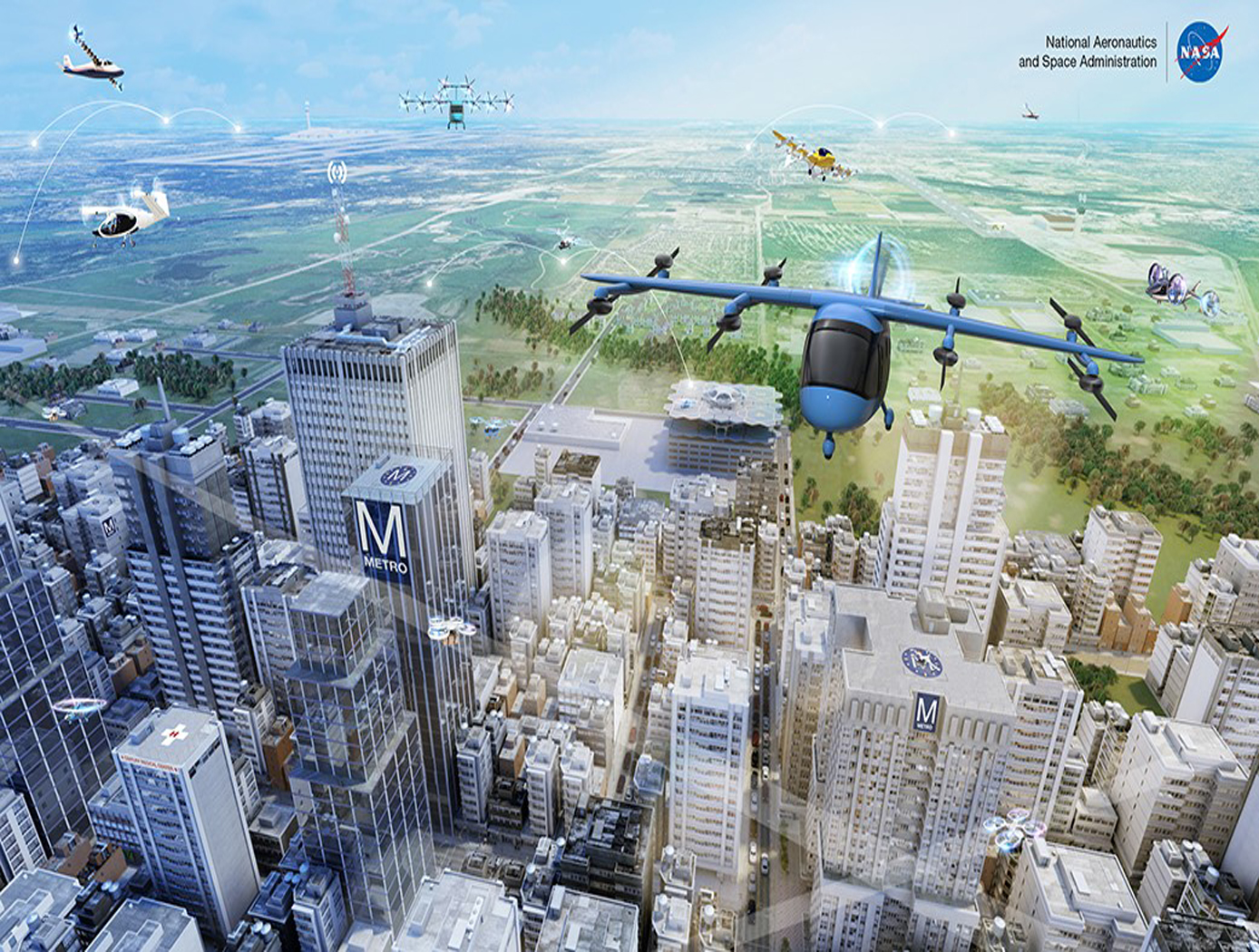
The term Advanced Air Mobility (AAM) refers to a new mode of transportation utilizing highly automated airborne vehicles for transporting goods and/or people. The adoption of widespread use of AAM vehicles will necessitate a network of vertiports located throughout a geographical region. A vertiport refers to a physical structure for the departure, arrival, and parking/storage of AAM vehicles. NASA-developed Vertiport Assessment and Mobility Operations System (VAMOS!) enables identifying geographical locations suitable for locating a vertiport or assessing suitability of pre-selected locations. For example, suitability evaluation factors include zoning, land use, transit stations, fire stations, noise, and time-varying factors like congestion and demand.
The vertiport assessment system assigns suitability values to these factors based on user-input, and types, including location-based (e.g., proximity to mass transit stations), level-based (e.g., noise levels), characteristic-based (e.g., residential zoning), and time-based (e.g., demand). Based on user input, the system spreads a grid over the geographical area, specifies importance criteria and weights for scaling the impact of the suitability factors, and identifies specific sub-regions as candidate locations. The candidate sub-regions are shown on a user interface map overlay in a color-coded gradient that reflects the suitability strength for a sub-region. Vertiport locations are selected within these sub-regions. These candidate vertiport locations are refined by establishing feasibility of flight between them. VAMOS! includes a modeling component and a simulation component. The modeling component assists a user to identify one or more geographical locations at which a vertiport may be physically built. The simulation component of the technology displays, in real-time, the simulated operational behavior of AAM vehicles and in the context of their projected flight paths combined with data dynamically obtained from live sources. These data sources can be from the Federal Aviation Administration (FAA) or other private or public governing bodies, from one or more AAM vehicles in flight, and from weather sources.
Aerospace

Wind-Optimal Cruise Airspeed Mode for Flight Management Systems (FMS)
The novel approach for optimizing airspeed for both actual and predicted wind conditions in electric Vertical Takeoff and Landing (eVTOL) aircraft with Distributed Electric Propulsion (DEP) systems includes the process of creating a lookup table for wind‐optimal airspeed as a function of wind magnitude, considering the direction of the wind relative to the cruise segment, considering the cruise altitude for an aircraft type, and incorporating the wind-optimal airspeed lookup table in the performance database for real‐time access by the Flight Management Systems (FMS) to predict wind-optimal airspeed at waypoints of the flight plan. The target wind‐optimal airspeed is updated in real-time throughout the cruise portion of a flight.
In a test of the wind-optimal airspeed targeting technique using a multi-rotor aircraft model, results obtained show benefits of flying at the wind‐optimal cruise airspeed compared to the best‐range airspeed. In headwind conditions, energy consumption was reduced by up to 7.5%, and flight duration was reduced by up to 28%. Under uncertain wind magnitudes, flying at wind-optimal airspeed offered lower variability and higher predictability in energy consumption than flying at best‐range airspeed.
Robotics Automation and Control

Anonymous Feature Processing for Enhanced Navigation
This concept presents a new statistical likelihood function and Bayesian analysis update for non-standard measurement types that rely on associations between observed and cataloged features. These measurement types inherently contain non-standard errors that standard techniques, such as the Kalman filter, make no effort to model, and this mismodeling can lead to filter instability and degraded performance.
Vision-based navigation methods utilizing the Kalman filter involve a preprocessing step to identify features within an image by referencing a known catalog. However, errors in this pre-processing can cause navigation failures. AFP offers a new approach, processing points generated by features themselves without requiring identification. Points such as range or bearing are directly processed by AFP.
Operating on finite set statistics principles, AFP treats data as sets rather than individual features. This enables simultaneous tracking of multiple targets without feature labeling. Unlike the sequential processing of the Kalman filter, AFP processes updates in parallel, independently scoring each output based on rigorous mathematical functions. This parallel processing ensures robust navigation updates in dynamic environments, and without requiring an identification algorithm upstream of the filter.
Computational simulations conducted at Johnson Space Center demonstrate that AFP's performance matches or exceeds that of the ideal Kalman filter, even under non-ideal conditions. Anonymous Feature Processing for Enhanced Navigation is at a technology readiness level (TRL) 4 (component and/or breadboard validation in laboratory environment) and is now available for patent licensing. Please note that NASA does not manufacture products itself for commercial sale.
Aerospace
Active Turbulence Suppression System for Electric Vertical Take-Off and Landing (eVTOL) vehicles
The Active Turbulence Suppression (ATS) system for electric Vertical Take-Off and Landing (eVTOL) vehicles employ existing lifting propellers to dampen instabilities during flight, such as Dutch-roll oscillations and other gust-induced oscillations. When a roll angle of an eVTOL aircraft has deviated or is about to deviate from a current stable aircraft state to an undesirable, unstable, and oscillating aircraft state, the ATS system queries a turbulence suppression database that stores a set of propeller speed profiles for mitigation a deviation of a given roll angle for a particular aircraft with specified propellers. Using this data, the eVTOL flight controller adjusts the speed of the propellers for a certain duration of time, according to the propeller speed profiles for mitigating the deviation. In models of aircraft with adjustable propeller angles, the database includes blade angle profiles for mitigating the effects of turbulent conditions. Timing and rate of propeller activation can be pre-computed using higher order computational modeling performed with NASA’s super computing resources. Because the data is pre-computed, the use of the ATS system onboard does not require significant computing resources to implement on eVTOL vehicles. The technology, a mechanism by which existing eVTOL propellers are leveraged to suppress gust-induced oscillations enables a safe and comfortable passenger experience at low-cost and without added hardware.
Sensors

Thin Film Sensor for Ultra High-Temp Measurement
The thin film sensor’s principal advantage lies in its potential to take high frequency temperature measurements from the surface of a reentering spacecraft while simultaneously withstanding the high temperature and oxidizing environment encountered. This data provides engineers with operational phase measurements used to refine the spacecraft’s operational envelope and track flight hardware behavior in addition to providing high frequency temperature measurements that can inform the physics of a boundary layer.
Mismatches in coefficients of thermal expansion (CTE) are expected in TPS-based sensor applications because the metallic materials used for temperature sensing have thermal expansion rates that differ from the rates of the substrate and coating materials in the TPS. At high temperatures during reentry, this mismatch in CTE can create a significant strain differential between the metallic sensor, sensor leads, and the materials to which the sensor and leads are bonded.
High frequency response temperature measurements on the surface of entry spacecraft are not currently possible above ~700 F with existing measurement capabilities. This shortcoming is primarily due to the need for robust sensor behavior at temperatures of several thousand degrees F. The sensor design of this technology preserves the integrity of sensor components while enhancing its high temperature functionality.
The thin film temperature sensor has a technology readiness level (TRL) 5 (Component and/or breadboard validation in relevant environment) and is now available for patent licensing. Please note that NASA does not manufacture products itself for commercial sale.

