Search
manufacturing

Plasma Deposition of Metal in Composite Panels
NASA's plasma-deposition process provides the ability to tailor various properties while designing functional parts by selecting specific materials and processing parameters to meet the end goal. Specifically, the plasma process deposits metal particles that are heated as they travel axially at low velocity through an inert gas plasma. The accelerated powder particles become molten, strike the substrate fabric (uniaxial, biaxial, and multiaxial) and rapidly solidify, imparting very little heat to the substrate while forming a metal-to-fiber bond, as well as a metal-to-metal bond. The resulting metal-coated fabric is porous, so the polymer matrix can pass through the product precursor during the infusion process. The amount of metal deposited can be
controlled, as can the number of plies of fabric that are ultimately stacked to produce the preform for the polymer matrix infusion process. A variety of infusion processes can be utilized to prepare the FML, including resin transfer molding (RTM), resin film infusion (RFI), and vacuum-assisted resin transfer molding (VARTM). The tailorable aspect of the process allows for specific product design. By varying the combination of metal particle, fiber, fabric type, metal layer thickness, fabric direction, number of layers, polymer matrix resin, infusion process, and cure conditions, the characteristics of the final part can meet the needs of various applications.
information technology and software

A Method For Developing And Maintaining Evolving Systems With Software Product Lines
The idea of a software product line has been developed that views software products that are substantially similar, or which have substantially similar content, as being different products in a line of products that the organization develops. For example, flight software for different missions can be viewed as a line of products that fulfills this purpose, with many of the products having similarities, or in extreme cases being very similar with a few specializations.
This method expands this view further and sees an evolving system, one that will likely run for a long period of time, and which must have corrections, enhancements and changes made to it over a period of time, as essentially exhibiting a product line. More specifically, different versions or releases of the system are viewed as different 'products' that are substantially similar. This method opens a new field of developing a complex system that is likely to involve many interacting components for development as a product line, which can be developed with state-of-the-art software engineering techniques.
Materials and Coatings

Advanced Isothermally Produced Next-Gen Composites
Next generation aircraft are anticipated to be largely made with composite components, requiring significant increases in manufacturing rates of composites to meet the demand for a new fleet of aircraft. The higher rate manufacturing will require multiple advances, including rapid curing and lower processing temperatures. These requirements can be enabled by new processing methods such as isothermal rapidly cured composite parts.
NASA has developed materials and methods that meet those stringent requirements for high-rate manufacturing. The innovators have demonstrated at least two families of new resin formulations that meet the expected high-rate manufacturing needs. These new formulations have been engineered to be infused and cured at the same (i.e., isothermal) temperature, below that of commercially available materials. The materials can then be removed from the mold while still hot without distorting the shape, thereby reducing the processing times by eliminating the need for cooling to occur in the mold. After a post-cure process - which takes 4 hours or less and can be performed in batches - the mechanical properties of NASA's next-gen composites.
The related patent is now available to license. Please note that NASA does not manufacturer products itself for commercial sale.
mechanical and fluid systems

Compact Vibration Damper
Structural vibrations frequently need to be damped to prevent damage to a structure. To accomplish this, a standard linear damper or elastomeric-suspended masses are used. The problem associated with a linear damper is the space required for its construction. For example, if the damper's piston is capable of three inches of movement in either direction, the connecting shaft and cylinder each need to be six inches long. Assuming infinitesimally thin walls, connections, and piston head, the linear damper is at least 12 inches long to achieve +/-3 inches of movement. Typical components require 18+ inches of linear space. Further, tuning this type of damper typically involves fluid changes, which can be tedious and messy. Masses suspended by elastomeric connections enable even less range of motion than linear dampers.
The NASA invention is for a compact and easily tunable structural vibration damper. The damper includes a rigid base with a slider mass for linear movement. Springs coupled to the mass compress in response to the linear movement along either of two opposing directions. A rack-and-pinion gear coupled to the mass converts the linear movement to a corresponding rotational movement. A rotary damper coupled to the converter damps the rotational movement. To achieve +/- 3 inches of movement, this design requires slightly more than six inches of space.
information technology and software
Inductive Monitoring System
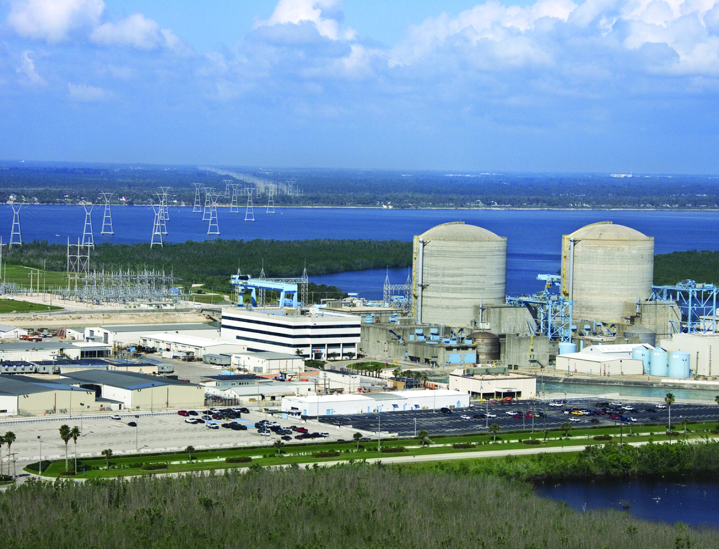
The Inductive Monitoring System (IMS) software provides a method of building an efficient system health monitoring software module by examining data covering the range of nominal system behavior in advance and using parameters derived from that data for the monitoring task. This software module also has the capability to adapt to the specific system being monitored by augmenting its monitoring database with initially suspect system parameter sets encountered during monitoring operations, which are later verified as nominal. While the system is offline, IMS learns nominal system behavior from archived system data sets collected from the monitored system or from accurate simulations of the system. This training phase automatically builds a model of nominal operations, and stores it in a knowledge base. The basic data structure of the IMS software algorithm is a vector of parameter values. Each vector is an ordered list of parameters collected from the monitored system by a data acquisition process. IMS then processes select data sets by formatting the data into a predefined vector format and building a knowledge base containing clusters of related value ranges for the vector parameters. In real time, IMS then monitors and displays information on the degree of deviation from nominal performance. The values collected from the monitored system for a given vector are compared to the clusters in the knowledge base. If all the values fall into or near the parameter ranges defined by one of these clusters, it is assumed to be nominal data since it matches previously observed nominal behavior. The IMS knowledge base can also be used for offline analysis of archived data.
mechanical and fluid systems
Feedthrough for Severe Environments and Temperatures
Space and ground launch support related hardware often operate under extreme pressure, temperature, and corrosive conditions. When dealing with this type of equipment, it is frequently necessary to run wiring, tubes, or fibers through a barrier separating one process from another with one or both operating in extreme environments. Feedthroughs used to route the wiring, tubes, or fibers through these barriers must meet stringent sealing and leak tightness requirements.
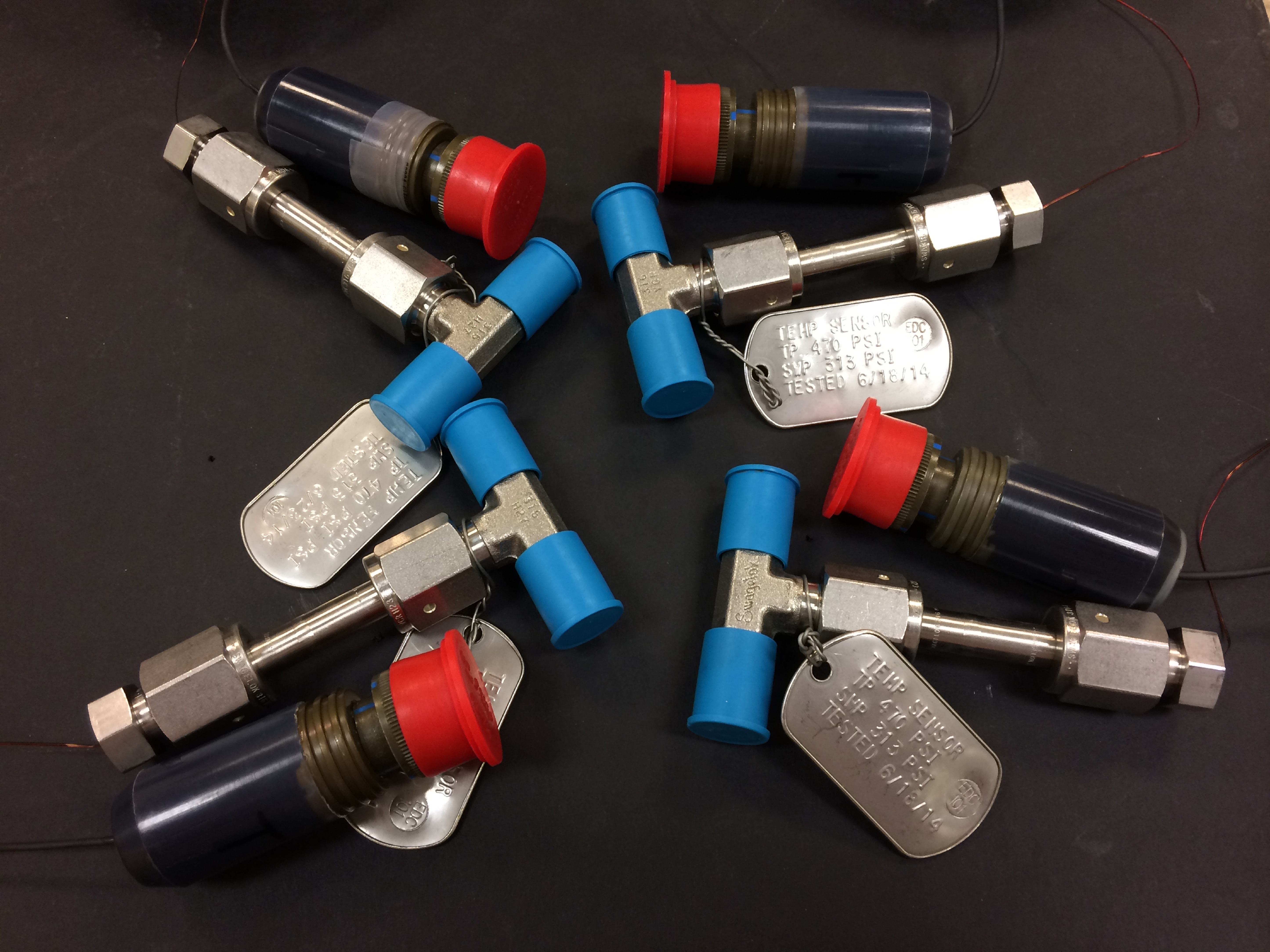
This affordable NASA feedthrough meets or exceeds all sealing and leak requirements utilizing easy-to-assemble commercial-off-the-shelf hardware with no special tooling. The feedthrough is a fully reconfigurable design; however, it can also be produced as a permanent device. Thermal cycling and helium mass spectrometer leak testing under extreme conditions of full cryogenic temperatures and high vacuum have proven the sealing capability of this feedthrough with or without potting (epoxy fill) on the ends. Packing material disks used in the construction of the device can be replaced as needed for rebuilding a given feedthrough for another job or a different set of feeds if potting is not used for the original feedthrough build. (Potting on one or both sides of the sleeve provides double or triple leak sealing protection). Variable Compression Ratio (VCR) connectors were adapted for the pressure seal on the feedthrough; however, any commercial connector can be similarly adapted. The design can easily be scaled up to larger (2" diameter) and even very large (12" or more) sizes.
mechanical and fluid systems
Full-Size Reduced Gravity Simulator For Humans, Robots, and Test Objects
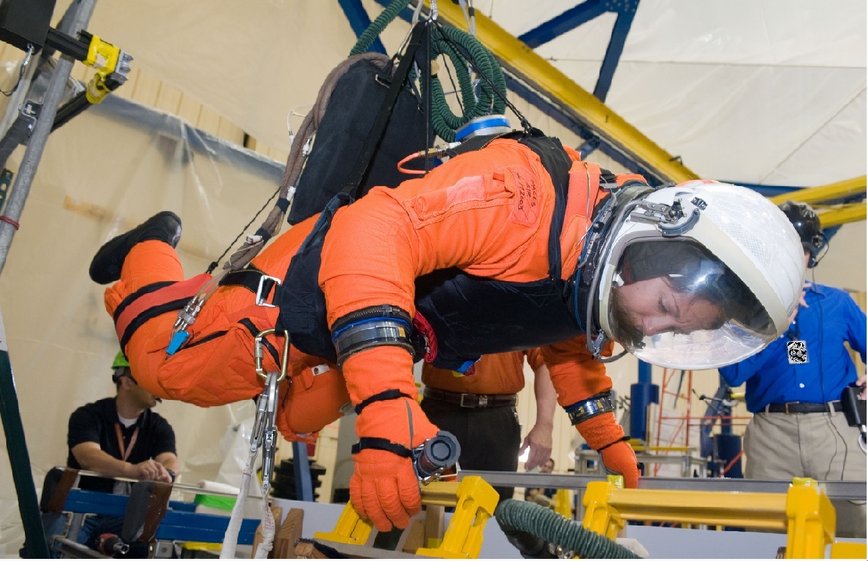
The Active Response Gravity Offload System (ARGOS) provides a simulated reduced gravity environment that responds to human-imparted forces. System capabilities range from full gravity to microgravity. The system utilizes input/feedback sensors, fast-response motor controllers, and custom-developed software algorithms to provide a constant force offload that simulates reduced gravity.
The ARGOS system attaches to a human subject in a gimbal and/or harness through a cable. The system then maintains a constant offload of a portion of the subjects weight through the cable to simulate reduced gravity. The system supports movements in all 3 dimensions consistent with the selected gravity level. Front/back and left/right movements are supported via a trolley on an overhead runway and bridge drive system, and up/down movements are supported via a precisely positioned cable. The system runs at a very high cycle rate, and constantly receives feedback to ensure the human subjects safety.
Electrical and Electronics
In Situ Wire Damage Detection and Rerouting System
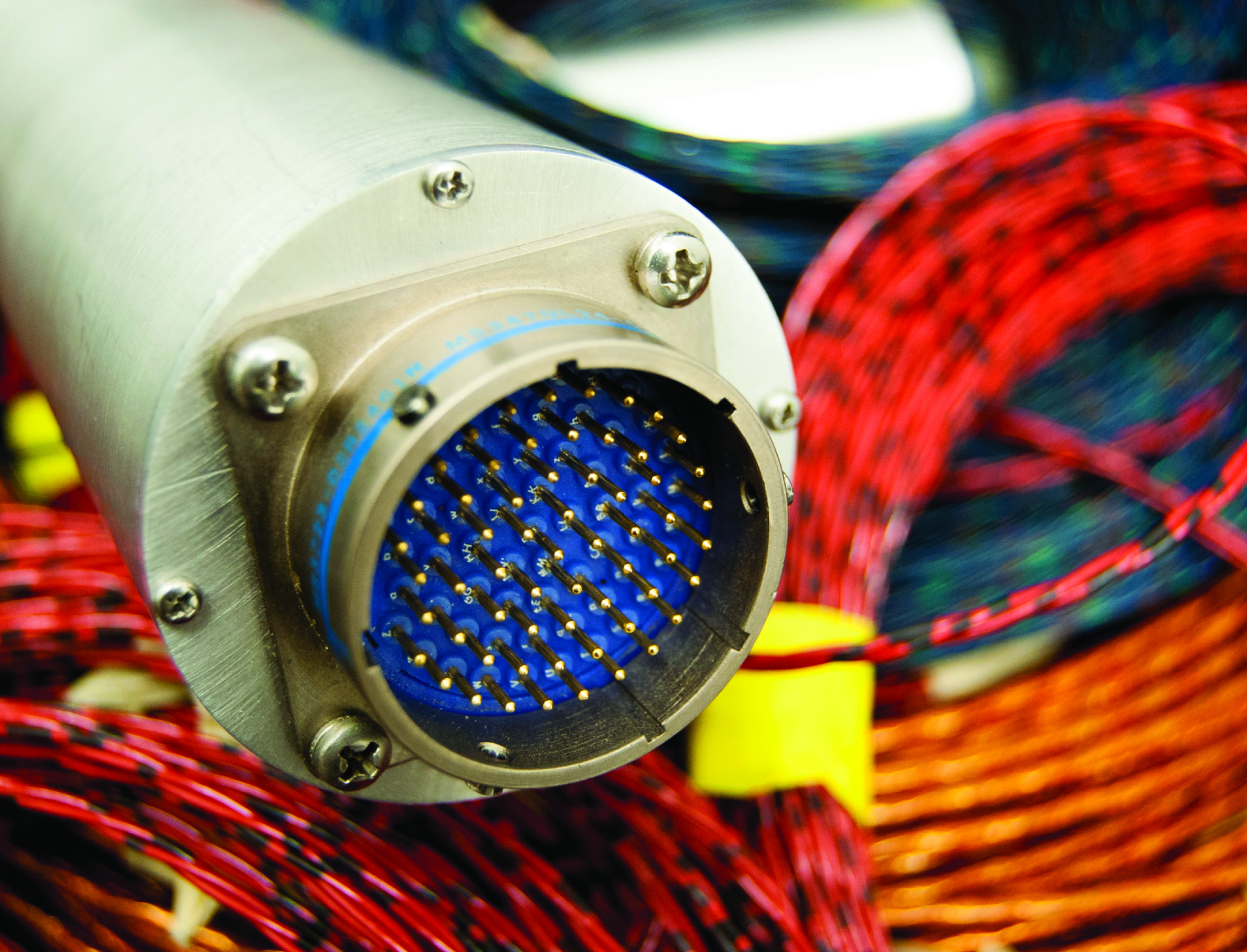
The tester was designed to monitor electrical faults in either online or offline modes of operation. In the online mode, wires are monitored without disturbing their normal operation. A cable can be monitored several times per second in the offline mode, and once per second in the online mode. The online cable fault locator not only detects the occurrence of a fault, but also determines the type of fault (short/open/intermittent) and the location of the fault. This enables the detection of intermittent faults that can be repaired before they become serious problems. Since intermittent faults occur mainly during operations, a built-in memory device stores all relevant fault data. This data can be displayed in real time or retrieved later so maintenance and repairs can be completed without spending countless hours attempting to pinpoint the source of the problem.
Hardware and algorithms have also been developed to safely, efficiently, and autonomously transfer electrical power and data connectivity from an identified damaged/defective wire in a cable to an alternate wire path. This portion of the system consists of master and slave units that provide the diagnostic and rerouting capabilities. A test pulse generated by the master unit is sent down an active wire being monitored by the slave unit. When the slave unit detects the test pulse, it routes the pulse back to the master unit through a communication wire. When the master unit determines that a test pulse is not being returned, it designates that wire as faulty and reroutes the circuit to a spare wire.
Manufacturing
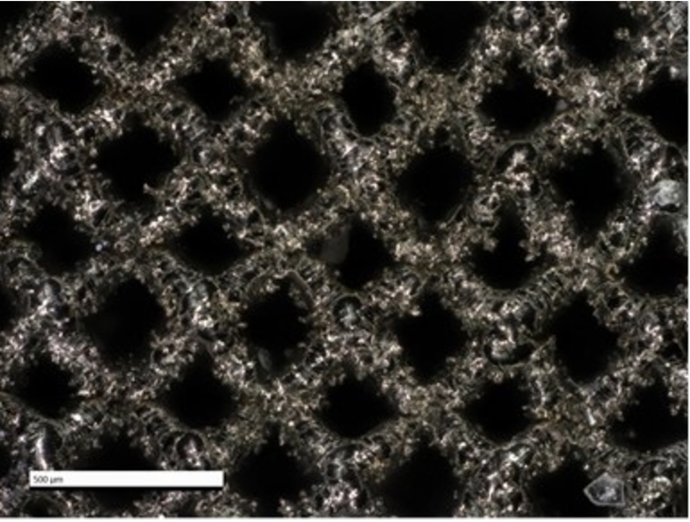
Additively Manufactured Propulsion Catalysts
Working with EOS, a market leader in additive manufacturing (AM) technology, NASA has pioneered the use of AM to achieve improved performance and cost reduction of propulsion catalyst systems. As mentioned above, conventional mono-propulsion catalysts are comprised of ceramic or graphite foams, which possess thousands of irregular pores with non-uniform size and distribution. Due to the lack of granular control in the manufacturing process, such foams are limited in terms of feasible designs. These foams also exhibit anisotropic mechanical properties and inconsistent fluid flow behavior. Furthermore, such catalysts are produced by a limited number of vendors, constraining availability and inflating cost. As with several other aerospace structures, AM of mono-propulsion catalysts enables increased manufacturing capabilities (e.g., granular geometric control, repeatability) while reducing cost and lead time.
NASA and EOS leveraged AM to generate ultra-fine lattice structures – repeating unit cells with ligament thickness as small as 100 microns – to replace coated ceramic or graphite foam catalysts. These AM lattice structures offer several advantages including increased control of structure topology, unconstrained designed flexibility, improved compressive strength, and fluid flow optimization – all printed into a single component from a preferred refractory platinum metal. Granular control of structure topology allows for tailored percent relative density (%RD), which in turn allows manufacturers to control the mechanical and fluid flow properties of the final catalyst structure. In other words, NASA’s AM ultra-fine lattice catalyst structures significantly improve upon the drawbacks of conventional catalysts by offering a higher degree of control over the structure, enabling the generation of catalysts with customized material properties. In addition, the use of AM ensures the catalysts exhibit high spatial symmetry and can be generated in a repeatable (non-stochastic) manner, all while reducing cost and lead times.
While NASA and EOS' ultra-fine lattice structures were originally developed for mono-propellant systems (e.g., green propellant thruster catalysts), the same structures and manufacturing technologies can be applied to liquid or gas permeable rigid materials, evaporative film cooling heat exchangers, filtering, and other applications.
manufacturing

AERoBOND: Large-scale Composite Manufacturing
This technology (AERoBOND) enables the assembly of large-scale, complex composite structures while maintaining predictable mechanical and material properties. It does so by using a novel barrier-ply technology consisting of an epoxy resin/prepreg material with optimal efficiency, reliability, and performance. The barrier-ply materials prevent excessive mixing between conventional composite precursors and stoichiometrically-offset epoxy precursors during the cure process by forming a gel early in the cure cycle before extensive mixing can occur. The barrier ply is placed between the conventional laminate preform and the stoichiometrically-offset ply or plies placed on the preform surface, thus preventing excessive mass transfer between the three layers during the cure process. In practice, the barrier ply could be combined with the offset ply to be applied as a single, multifunctional surfacing layer enabling unitized assembly of large and complex structures. The AERoBOND method is up to 40% faster than state-of-the-art composite manufacturing methods, allows for large-scale processing of complex structures, eliminates the potential for weak bond failure modes, and produces composites with comparable mechanical properties as compared with those prepared by co-cure.


