Search
Sensors

Hyper-Distributed RFID Antenna (HYDRA) System
Components of the HYDRA system include an RFID reader (aka an RFID transceiver or interrogator), RF cables, antennas, and one or more Intelligent Multiplexer Modules (IMMs). The IMM is the core building block of the HYDRA system. In one of its basic embodiments, the IMM comprises an RF directional coupler, RF switch, RFID chip, micro-controller, and power generation and management hardware. In this basic implementation, a single RF port from the RFID reader is attached to the IMM and transfers power thereto. Internally within the IMM, the RF directional coupler diverts a small amount of RF power to rectification and power management circuitry for conversion to DC power that drives the RFID chip, microcontroller, and RF switch. The RFID chip enables communication with the RFID reader and allows the reader to administer changes to the microcontroller‘s embedded software. The microcontroller controls the RF switch, which passes power along to one or more output channels. Connections to the output channels can include antennas, additional IMMs, or other sensors.
The HYDRA system may include numerous alternate embodiments to enhance and customize the basic functionality. In one embodiment, the microcontroller is replaced with a simple timer. In another embodiment, the switch has multiple output ports to connect to a distributed chain of HYDRA system or local antennas. Also, the entirety of RF power exiting a HYDRA module can be rectified and used to power a local sensor node, which could be implemented via WiFi or Bluetooth Low Energy (BLE). Features of the HYDRA system include the ability to cover both open regions and enclosures, the ability to switch RF power to an unused load for assisting in the resolution of tag antenna ambiguities, and the ability to accept plug-and-play add-ons such that the reader’s software can use the system without requiring any embedded modifications.
The HYDRA system is technology readiness level (TRL) 7 (system prototype demonstrated in an operational environment) and is now available for patent licensing. Please note that NASA does not manufacture products itself for commercial sale.
Sensors
Low Mass Antenna Boosts RFID Device Performance
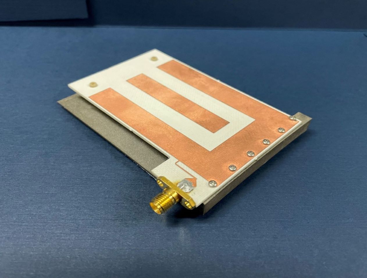
NASA’s HYDRA system enables a new approach in routing the RFID signal, greatly increasing extensibility and the number of antennas that can be served by a single reader. However, increasing the number of antennas in any environment is often undesirable unless the antenna size is inconspicuous. Basing this RFID dual mode antenna on a quarter-wavelength structure allows it to be smaller than an antenna designed for half-wavelength structure, reducing overall mass.
NASA’s RFID dual mode antenna is enabled by utilizing two different types of resonance modes – a “slot” mode and a microstrip “patch” mode. An innovative feed architecture allows for coupling from the RFID reader into both modes, with the impedance of each mode approximately equal at respective resonant frequencies. The antenna is designed such that each mode resonates at a different portion of the operating bandwidth, and further with each mode radiating an orthogonal polarization to the other. Frequency-hopping RFID protocols, used in conjunction with this antenna, result in the polarization diversity required for readers to reliably communicate with arbitrarily oriented RFID tags.
Numerous commercial applications exist for this RFID dual mode antenna. Examples may include usage in a multiple antenna architecture that is connected to a single reader in an open-air region, in a small, enclosed region such as a cabinet drawer, or through a combination of open and closed regions.
This RFID dual mode antenna has a technology readiness level (TRL) 7 (system prototype demonstrated in an operational environment) and is now available for patent licensing. Please note that NASA does not manufacture products itself for commercial sale.
Sensors

RFID Range Extension and Priority Data Forwarding
This novel technology builds upon a previously (NASA-developed) store-and-forward overlay architecture using COTS RFID protocols for BAP devices. It enables the range-extension and priority forwarding of critical sensor-collected data, even when an RFID interrogator is not in range. With this method, an RFID sensor maintains data queues of varying priority, maintaining at least one high priority queue.
When high priority data is collected, the RFID sensor activates a BAP mode that enhances the effective range of the RFID link to the interrogator. After high priority queues are cleared, BAP mode is deactivated to preserve onboard battery life and passive RFID operations resume for proximity-based data delivery.
This technology may deliver the most value in applications where long battery lifetime and remote sensing/data collection are essential and when regularly scheduled data transfer may not be available or possible if the target is out of the normal coverage area. The RFID sensor tags described here can operate in a low to no power mode and collect data until a trigger or threshold value is measured. At this time, the critical data can be transmitted from outside passive RFID coverage areas to the nearest interrogator.
Although this technology was developed to enhance the effective range of CO2 sensors worn by astronauts aboard the International Space Station, it could find additional applications in food, pharmaceutical, and other industries whose perishable and/or fragile goods rely on a stable climate throughout the transport and storage lifecycle.
Sensors
Passive Smart Container
Passive Smart Container system comprises four major components: RFID circuits embedded in or around the container, an antenna and RF distribution system, and an interrogator/reader. The system uses passive RFID circuits placed on a bulk item container to track consumption and quantify items as the items are removed, added or replaced in the container. The antenna is strategically integrated with the lid or elsewhere in or around the container and is constantly coupling RFID signals to/from the RFID circuits. The circuits reply with information regarding the fill level in the container. A processor connected to the reader/interrogator can infer the fill level according to which RFID circuits respond and the magnitude and phase of the returned signals. The technology is compatible with the EPCglobal Class-1 Generation-2 RFID standard. This setup can be modified to track all kinds of items, large and small, making this technology suitable and applicable to an array of commercial fields.
RFID is a disruptive technology that has made a large impact on several industries, especially in supply chain and asset management. Passive Smart Container is well positioned to tap into this growing market. Its ability to account for discrete items as well as liquids and bulk goods that were deemed impossible or impractical to tag makes this technology relevant for an array of applications and industries.
Sensors

RFID Tags Collaborate for Data Retrieval
Commonly used RFID protocols are widely accepted because they are inexpensive and easy to implement. However, the associated low transmit power and narrow bandwidth typically result in coarse local-ization estimates. Often it is desirable to know the precise location of assets without reverting to an entirely different and more expensive protocol. Additionally, many industrial and other applications may desire technology that confirms the mating of components. This new program-mable sensor tag technology facilitates both precise localization and mating confirmation in-part by allowing the RFID sensor tag to become a type of distributed low-cost reader.
To determine a tag attachment, this innovation utilizes a fixed location RFID sensor tag that incorporates a receptacle node to measure an electrical “influence” through resistance, capacitance, inductance, etc. Assets for which localization is desired are outfitted with “influence tags” – devices that produce a set of distinguishable responses when placed in the receptacle region of the RFID sensor tag. Mating or connections are confirmed when electrodes from an influence tag become attached to matching electrodes on a sensor tag’s receptacle node. Information obtained by the RFID sensor tag is stored in its local memory bank through which a dedicated reader can retrieve influence tag information.
Potential applications exist for this technology where specific assets need to be precisely located and/or confirmation is needed when two parts have been correctly connected or attached. This RFID tag technology allows the retrieval of inventory status information in an energy efficient manner from inexpensive, small form factor hardware. Robotic retrieval of assets can be more easily facilitated with this innovation.
communications

Smart Enclosure using RFID for Inventory Tracking
The smart enclosure innovation employs traditional RFID cavities, resonators, and filters to provide standing electromagnetic waves within the enclosed volume in order to provide a pervasive field distribution of energy. A high level of read accuracy is achieved by using the contained electromagnetic field levels within the smart enclosure. With this method, more item level tags are successfully identified compared to approaches in which the items are radiated by an incident plane wave. The use of contained electromagnetic fields reduces the cost of the tag antenna; making it cost-effective to tag smaller items.
RFID-enabled conductive enclosures have been previously developed, but did not employ specific cavity-design techniques to optimize performance within the enclosure. Also, specific cavity feed approaches provide much better distribution of fields for higher read accuracy. This technology does not restrict the enclosure surface to rectangular or cylindrical shapes; other enclosure forms can also be used. For example, the technology has been demonstrated in textiles such as duffle bags and backpacks. Potential commercial applications include inventory tracking for containers such as waste receptacles, storage containers, and conveyor belts used in grocery checkout stations.
Communications

Real-Time Tracking System
The innovation builds upon conventional UWB hardware by incorporating tracking methodology and algorithms in addition to external amplifiers for signal boost. The tracking methodology is a triangulation calculation consisting of Angle of Arrival (AOA) and Time Difference of Arrival (TDOA) using a cross-correlation peak detection method. By directly estimating TDOA information from UWB pulses, the method achieves the high temporal resolution (on the order of picoseconds) needed to measure AOA with extreme precision. The system uses a PC to synchronize and process data in real time from two receivers, or clusters, to display the position of the transmitter-equipped person or object. The interface software enables the PC to access the two data sets simultaneously through separate sockets. In the data collection process, data segments from each receiver are interleaved with those from the other receiver in chronological order of collection. Within the PC, the data segments are stored in a separate buffer; therefore, the contents of the buffers are representations of the same UWB pulse waveform arriving at the two receivers at approximately the same time. This data synchronization provides the separate and simultaneous collection of waveform data that the tracking algorithm requires for accurate real-time tracking.
communications

NanoWire Glass Switch for Radio Frequency
The nanoionic-based switches developed by NASA's Glenn Research Center exploit the properties of some amorphous materials that can incorporate relatively large amounts of metal and behave as solid electrolytes. As with liquid electrolytes found in lead-acid batteries, for example, solid electrolytes consist of mobile ions which undergo oxidation/reduction reactions at the anode and cathode of the system. The ionic conductivity of such a material can be of the same order of magnitude as the electronic conductivity of a semiconductor but without the drawbacks of an electromechanical device.
In the nanoionic switch, ions are formed at an anode and migrate into the solid electrolyte, while electrons are injected from a cathode, thereby causing the growth of metal nanowires through the electrolyte from the cathode to the corresponding anode when a positive DC bias is applied. Once a nanowire has grown sufficiently to form an electrically conductive path between the electrodes, the switch is closed and no electric power is needed to maintain the connection, unlike in a MEMS or semiconductor-based switch. Moreover, the process of making the connection can easily be reversed by applying a negative bias, causing the wires to ungrow and the switch to open. Thus, NASA's state-of-the-art device is a reversible electrochemical switch that can have geometric features as small as nanometers. The process time for making or breaking the connection is very brief -- about a nanosecond. In addition, this nanoionic material can be deposited in such a way to form multilayer control circuits, which has the potential to minimize circuit footprints, reduce overall circuit losses, and provide unprecedented ease of integration.
sensors

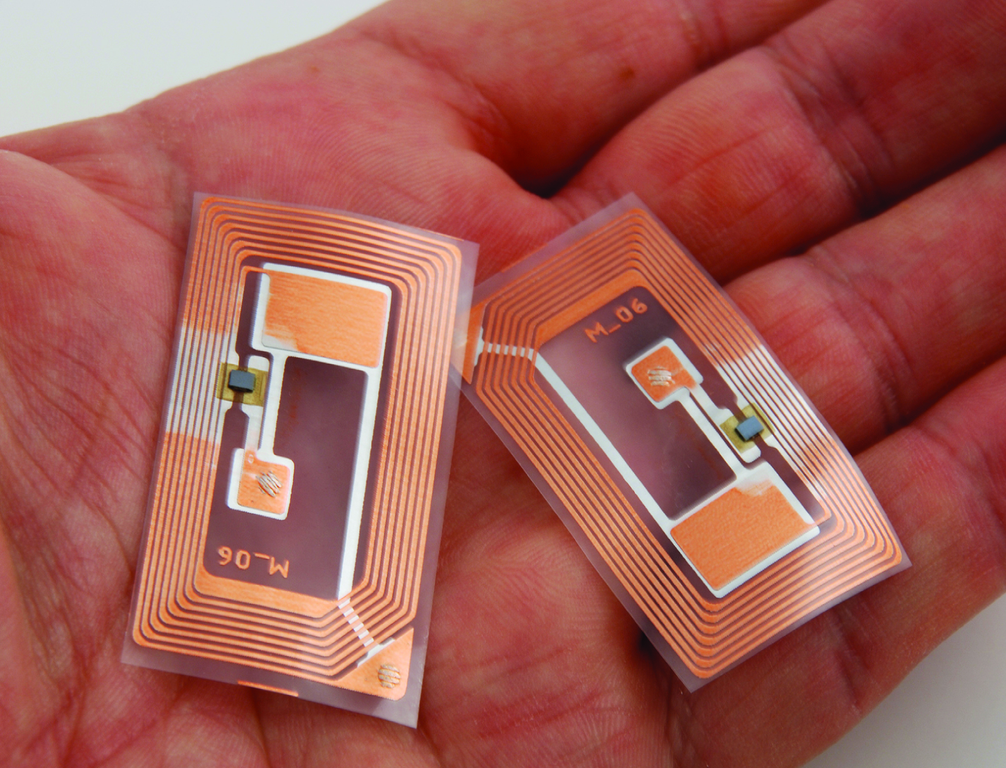
Wearable RFID Sensor Tags Yield Extended Operational Times
This technology exploits the inherently passive nature of RFID to approximate the services provided by traditional active Internet of Things (IOT) protocols like ZigBee and Bluetooth. A novel store-and-forward overlay on COTS RFID protocols allows an RFID active tags to transit through an ecosystem of RFID interrogators, exploiting contact opportunities as they arise and quietly transfers sensor readings at nearly no power cost to the RFID active tag. Specific intelligence built into both the interrogator and the tag leverages the RFID tag user memory (UM) as a stand-in IOT interface. The tag operates by sampling data into timestamped packets and loads them into tag memory. When an interrogator in the ecosystem realizes that a tag is in view and that there is unrecovered data on the tag, it takes custody of the sensor data packet and offloads the data into a database. A smart scheduler reads from the population of interrogators and schedules data transfers for specific tags when an interrogator can seed the custody transfer process for the data packets. NASA has produced working prototypes of wearables, worn by the crew aboard the International Space Station, that reports humidity, temperature and CO2 readings. In one estimate, the battery life is on pace to last an estimated nine years.
The Low-Power RFID to Collect and Store Data From Many Moving Wearable Sensors is a technology readiness level (TRL) 6 (system/subsystem prototype demonstration in a relevant environment). The innovation is now available for your company to license and develop into a commercial product. Please note that NASA does not manufacture products itself for commercial sale.
instrumentation

RFID-Enabled Wireless Instrumentation
With a form factor close to a deck of playing cards, the system interrogator has custom software to interface with and service a population of sensor tags at the required data rates. Each EPCglobal C1G2 sensor tag uses incident interrogator energy to charge its small integrated circuit (IC), which reads an internal memory bank, encodes identification data, and uses that information to modulate and backscatter a reply to the interrogator using reflected interrogator energy. Two tag interfaces allow the attached processor to power the reading/writing of data to the tag memory and then allows the interrogator to power the reading of the tag memory data. When neither of the two interfaces are engaged, the RFID IC is completely powered down. Reading and writing tag memory consumes relatively little power compared to the power draw of active transmitter/receiver protocols like Bluetooth, Zigbee, and Wi-Fi. Compared to passive sensing protocols, this wireless instrumentation system enables sampling of a larger population of tags without the computational burden associated with surface acoustic wave (SAW) sensing. RFID-Enabled Wireless Instrumentation technology allows the RFID interrogator to write data through the interface of a sensor tag memory bank using only interrogator power. With only minimal cost to the sensors power budget, the microcontroller unit can read that data out over the serial interface. The sensor can transmit and receive data at no effective cost to its small coin cell battery power supply.
This technology is readiness level (TRL) 8 (actual system completed and "flight qualified" through test and demonstration) and the innovation is now available for your company to license. Please note that NASA does not manufacture products itself for commercial sale.

