Search
materials and coatings
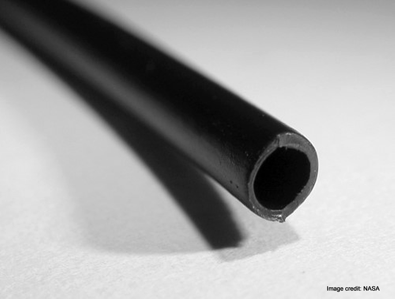
Origami-based Deployable Fiber Reinforced Composites
Deployable space structures often rely upon telescoping or folding structures that either must be manually deployed or deployed by attached motors. These structures are often made from heavier (relative to carbon fiber composites) metals to provide enough strength to support a load. As such, there is a need for in-space structures that are lightweight, can be packaged compactly, and can be deployed easily.
The composite material developed here does not require high temperature baking to cure the polymer, rather relying on UV light to solidify the polymer component. The composite is then included into origami-based structures that can fold and deploy using the polymer shape memory effect. The composite is first trained to assume the deployed structural shape when heated; it is then folded like origami and frozen into the packaged shape for storage and launch. Combining the composite material with the origami-inspired design leads to high strength structures (can hold at least 600 kg on Earth). To date, a ~5-inch prototype structural bar has been produced using the UV-curable composite and further development is on-going at NASA Langley.
The deployable origami composite structures are at technology readiness level (TRL) 4 (component and/or breadboard validation in laboratory environment) and are available for patent licensing.
Materials and Coatings

Advanced Materials for Electronics Insulation
Many researchers have attempted to use polymer-ceramic composites to improve the thermal and dielectric performance of polymer insulation for high voltage, high temperature electronics. However, using composite materials has been challenging due to manufacturing issues like incomplete mixing, inhomogeneous properties, and void formation. Here, NASA has developed a method of preparing and extruding polymer-ceramic composites that results in high-quality, flexible composite ribbons.
To achieve this, pellets of a thermoplastic (e.g., polyphenylsulfone or PPSU) are coated with an additive then mixed with particles of a ceramic (e.g., boron nitride or BN) as shown in the image below. After mixing the coated polymer with the ceramic particles, the blended material was processed into ribbons or films by twin-screw extrusion. The resulting ribbons are highly flexible, well-mixed, and void free, enabled by the coated additive and by using a particle mixture of micronized BN and nanoparticles of hexagonal BN (hBN).
The polymer-ceramic composite showed tunable dielectric and thermal properties depending on the exact processing method and composite makeup. Compared to the base polymer material, the composite ribbons showed comparable or improved dielectric properties and enhanced thermal conductivity, allowing the composite to be used as electrical insulation in high-power, high-temperature conditions.
The related patent is now available to license. Please note that NASA does not manufacturer products itself for commercial sale.
materials and coatings
Highly Thermal Conductive Polymeric Composites
There has been much interest in developing polymeric nanocomposites with ultrahigh thermal conductivities, such as with exfoliated graphite or with carbon nanotubes. These materials exhibit thermal conductivity of 3,000 W/mK measured experimentally and up to 6,600 W/mK predicted from theoretical calculations. However, when added to polymers, the expected thermal conductivity enhancement is not realized due to poor interfacial thermal transfer.
This technology is a method of forming carbon-based fillers to be incorporated into highly thermal conductive nanocomposite materials. Formation methods include treatment of an expanded graphite with an alcohol/water mixture followed by further exfoliation of the graphite to form extremely thin carbon nanosheets that are on the order of between about 2 and about 10 nanometers in thickness. The carbon nanosheets can be functionalized and incorporated as fillers in polymer nanocomposites with extremely high thermal conductivities.
Materials and Coatings

Advanced Isothermally Produced Next-Gen Composites
Next generation aircraft are anticipated to be largely made with composite components, requiring significant increases in manufacturing rates of composites to meet the demand for a new fleet of aircraft. The higher rate manufacturing will require multiple advances, including rapid curing and lower processing temperatures. These requirements can be enabled by new processing methods such as isothermal rapidly cured composite parts.
NASA has developed materials and methods that meet those stringent requirements for high-rate manufacturing. The innovators have demonstrated at least two families of new resin formulations that meet the expected high-rate manufacturing needs. These new formulations have been engineered to be infused and cured at the same (i.e., isothermal) temperature, below that of commercially available materials. The materials can then be removed from the mold while still hot without distorting the shape, thereby reducing the processing times by eliminating the need for cooling to occur in the mold. After a post-cure process - which takes 4 hours or less and can be performed in batches - the mechanical properties of NASA's next-gen composites.
The related patent is now available to license. Please note that NASA does not manufacturer products itself for commercial sale.
Instrumentation
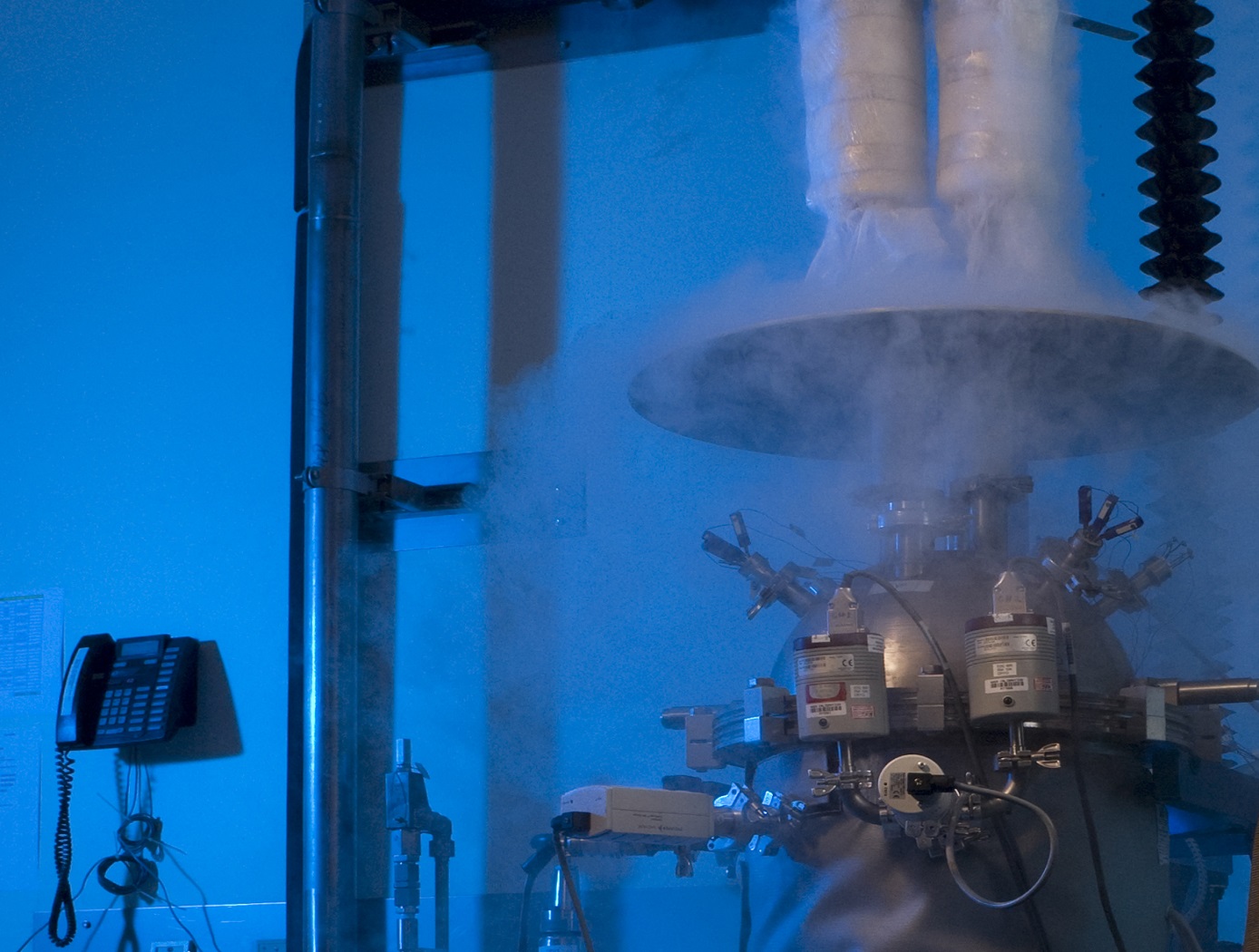
Cryostat-100
Cryostat-100 combines the best features of previous cryostats developed by NASA, while offering new features and conveniences. This unit can readily handle the full range of cryogenic-vacuum conditions over several orders of magnitude of heat flux. Guide rings, handling tools, and other design items make insulation change-out and test measurement verification highly reliable and efficient to operate. The new apparatus requires less ancillary equipment (it is not connected to storage tank, phase separator, subcooler, etc.) to operate properly. It is top-loading, which makes disassembly, change-out, and instrumentation hook-up much faster. The thermal stability is improved because of internal vapor plates, a single-tube system of filling and venting, bellows feed-throughs, Kevlar thread suspensions, and heavy-wall stainless-steel construction.
The cold mass of Cryostat-100 is 1m long, with a diameter of 168 mm. The test articles can therefore be of a corresponding length and diameter, with a nominal thickness of 25.4 mm. Shorter lengths are acceptable, and thicknesses may be from 0 mm to 50 mm. Tests are conducted from ambient pressure (760 torr) to high vacuum (below 110-4 torr) and at any vacuum pressure increment between these two extremes. The residual gas (and purge gas) is typically nitrogen but can be any purge gas, such as helium, argon, or carbon dioxide.
Typically, eight cold vacuum pressures are performed for each test series. The warm boundary temperature is approximately 293 K, and the cold boundary temperature is approximately 78 K. The delta temperature for the cryogenic testing is therefore approximately 215 K. A unique lift mechanism provides for change-out of the insulation test specimens. It also provides for maintenance and other operations in the most effective and time-efficient ways. The lift mechanism is also a key to the modularity of the overall system.
Propulsion
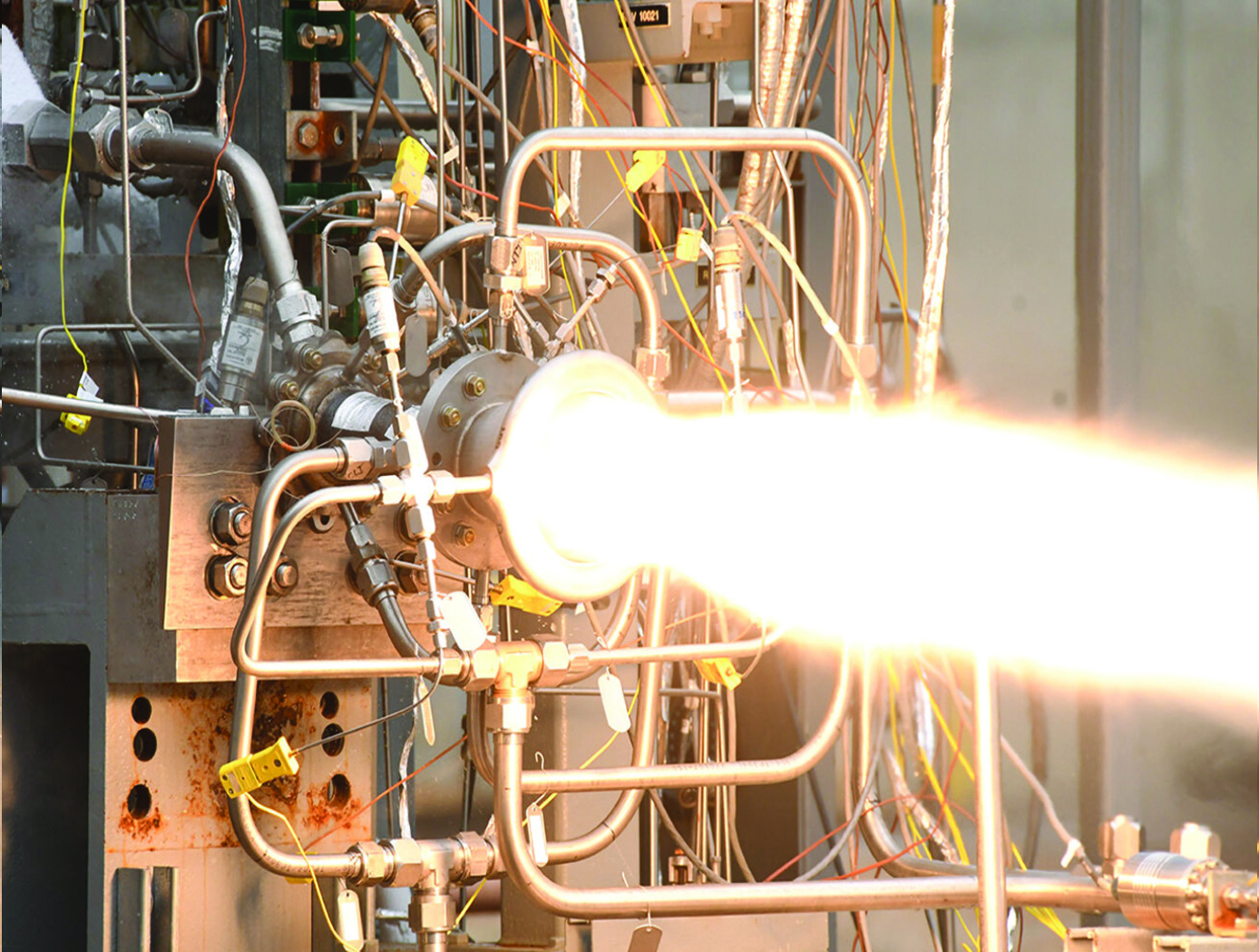
A One-piece Liquid Rocket Thrust Chamber Assembly
The one-piece multi-metallic composite overwrap thrust chamber assembly is centrally composed of an additively manufactured integral-channeled copper combustion chamber. The central chamber is being manufactured using a GRCop42 or GRCop84 copper-alloy additive manufacturing technology previously developed by NASA. A bimetallic joint (interface) is then built onto the nozzle end of the chamber using bimetallic additive manufacturing techniques. The result is a strong bond between the chamber and the interface with proper diffusion at the nozzle end of the copper-alloy. The bimetallic interface serves as the foundation of a freeform regen nozzle. A blown powder-based directed energy deposition process (DED) is used to build the regen nozzle with integral channels for coolant flow. The coolant circuits are closed with an integral manifold added using a radial cladding operation. To complete the TCA, the entire assembly including the combustion chamber and regen nozzle is wrapped with a composite overwrap capable of sustaining the required pressure and temperature loads.
sensors

Smart Skin for Composite Aircraft
When a lightning leader propagates through the atmosphere in the vicinity of an aircraft, the lightning electromagnetic emissions generated from the moving electrical charge will radiate the aircraft surface before the actual strike to the aircraft can occur. As the lightning leader propagates closer to the aircraft, the radiated emissions at the aircraft will grow stronger. By design, the frequency bandwidth of the lightning radiated is in the range for SansEC resonance. Hence the SansEC coil will be passively powered by the external oscillating magnetic field of the lightning radiated emission. The coil will resonate and generate its own oscillating magnetic and electric fields. These fields generate so-called Lorentz forces that influence the direction and
momentum of the lightning attachment and thereby deflect/spread where the strike entry and exit points/damage occurs on the aircraft.
Sensors
Electric Field Imaging System
The EFI imaging platform consists of a sensor array, processing equipment, and an output device. By registering voltage differences at multiple points within the sensor array, the EFI system can calculate the electrical potential at points removed from the sensor. Using techniques similar to computed tomography, the electrical potential data can be assembled into a three-dimension map of the magnitude and direction of electric fields. Since objects interact with electric fields differently based on their shape and dielectric properties, this electric field data can then be used to understand shape,
internal structure, and dielectric properties (e.g., impedance, resistance) of objects in three dimensions.
The EFI sensor can be used on its own to see electric fields or image electric fieldemitting objects near the sensor (e.g., to evaluate leakage from poorly shielded wires or casings). For evaluation of objects that do not produce an electric field, NASA has developed generator that emits a low-current, human-safe electrostatic field for snapshot evaluation of objects. Additionally, an alternative EFI system optimized to evaluate electric fields at significant distances (greater than 1 mile) is being developed for weather-related applications.
manufacturing
System for In-situ Defect Detection in Composites During Cure
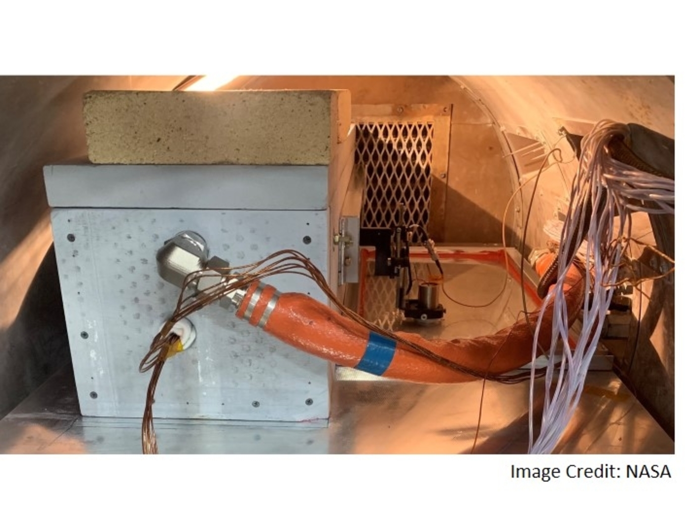
NASA's System for In-situ Defect (e.g., porosity, fiber waviness) Detection in Composites During Cure consists of an ultrasonic portable automated C-Scan system with an attached ultrasonic contact probe. This scanner is placed inside of an insulated vessel that protects the temperature-sensitive components of the scanner. A liquid nitrogen cooling systems keeps the interior of the vessel below 38°C. A motorized X-Y raster scanner is mounted inside an unsealed cooling container made of porous insulation boards with a cantilever scanning arm protruding out of the cooling container through a slot. The cooling container that houses the X-Y raster scanner is periodically cooled using a liquid nitrogen (LN2) delivery system. Flexible bellows in the slot opening of the box minimize heat transfer between the box and the external autoclave environment. The box and scanning arm are located on a precision cast tool plate. A thin layer of ultrasonic couplant is placed between the transducer and the tool plate. The composite parts are vacuum bagged on the other side of the tool plate and inspected. The scanning system inside of the vessel is connected to the controller outside of the autoclave. The system can provide A-scan, B-scan, and C-scan images of the composite panel at multiple times during the cure process.
The in-situ system provides higher resolution data to find, characterize, and track defects during cure better than other cure monitoring techniques. In addition, this system also shows the through-thickness location of any composite manufacturing defects during cure with real-time localization and tracking. This has been demonstrated for both intentionally introduced porosity (i.e., trapped during layup) as well processing induced porosity (e.g., resulting from uneven pressure distribution on a part). The technology can be used as a non-destructive evaluation system when making composite parts in in an oven or an autoclave, including thermosets, thermoplastics, composite laminates, high-temperature resins, and ceramics.
Materials and Coatings

Silicon Carbide (SiC) Fiber-Reinforced SiC Matrix Composites
Aimed at structural applications up to 2700°F, NASA's patented technologies start with two types of high-strength SiC fibers that significantly enhance the thermo-structural performance of the commercially available boron-doped and sintered small-diameter “Sylramic” SiC fiber. These enhancement processes can be done on single fibers, multi-fiber tows, or component-shaped architectural preforms without any loss in fiber strength. The processes not only enhance every fiber in the preforms and relieve their weaving stresses, but also allow the preforms to be made into more shapes. Environmental resistance is also enhanced during processing by the production of a protective in-situ grown boron-nitride (iBN) coating on the fibers. Thus the two types of converted fibers are called “Sylramic-iBN” and “Super Sylramic-iBN”.
For high CMC toughness, two separate chemical vapor infiltration (CVI) steps are used, one to apply a boron nitride coating on the fibers of the preform and the other to form the SiC-based matrix. The preforms are then heat treated not only to densify and shrink the CVI BN coating away from the SiC matrix (outside debonding), but also to increase its creep resistance, temperature capability, and thermal conductivity.
One crucial advantage in this suite of technologies lies in its unprecedented customizability. The SiC/SiC CMC can be tailored to specific conditions by down-selecting the optimum fiber, fiber coating, fiber architecture, and matrix materials and processes. In any formulation, though, the NASA-processed SiC fibers display high tensile strength and the best creep-rupture resistance of any commercial SiC fiber, with strength retention to over 2700°F.

