Search
Robotics Automation and Control
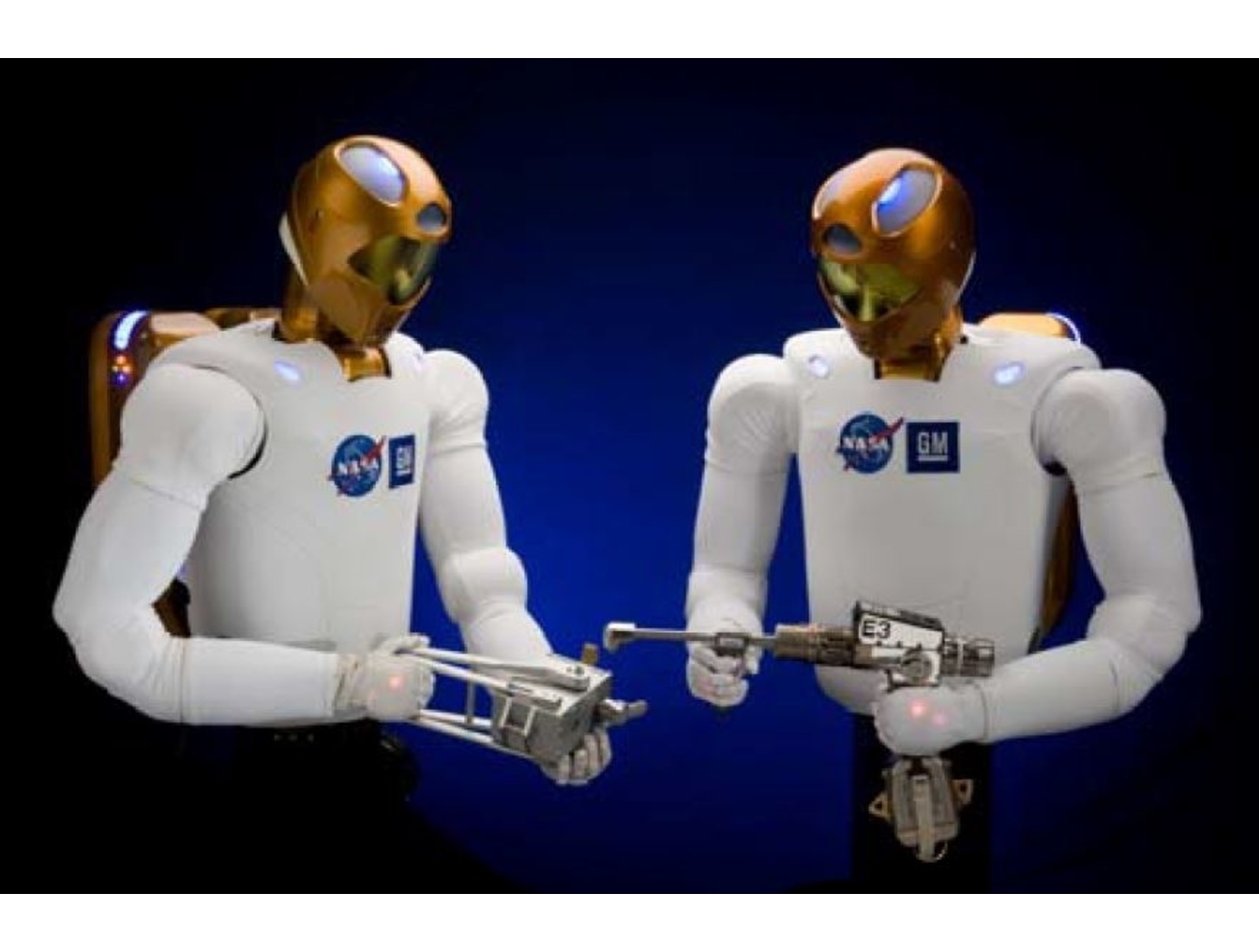
Advanced Humanoid Robotic Interface & Control
<i>Technologies for Safe Workspace Control of Humanoid Robots:</i> Safety is critical in scenarios where humans (e.g., factory workers or astronauts) are working in proximity to, or interacting with, R2. Methods for applying workspace limitations in velocity-controlled robotic mechanisms (U.S. Patent No. 8,676,382) and force or impedance-controlled robots (U.S. Patent No. 8,483,877) help to ensure such safety.
<i>Autonomous Control Systems for Humanoid Robotics:</i> A multiple priority operation space impedance control system (U.S. Patent No. 8,170,718) provides arm control, including programmable Cartesian stiffness. An interactive robot control architecture (U.S. Patent Nos. 8,364,314, and 8,260,460, and 8,706,299), including a simple GUI, provides an interactive development and work environment that integrates sensor data and feedback generated by R2. An additional system selects and controls appropriate manipulators to perform grasping operations (U.S. Patent No. 8,483,882).
<i>Humanoid Robotic Health Management System:</i> A diagnostics, prognostics, and health management system for human robotics (U.S. Patent No. 8,369,992) operates at all hardware and software levels of the robotic system, enabling system-wide observability, controllability, maintainability, scalability, and extensibility.
<i>Electromagnetic Motor Braking:</i> Electromagnetic fail-safe brakes (U.S. Patent No. 8,067,909) allow for selective, reliable braking of robotic motors (e.g., brushless DC motors) to ensure safe and effective operation.
<i>Highly Durable Connector Pin:</i> To address the high failure rate of connectors in robotic systems with flexible members, a highly durable connector pin (U.S. Patent No. 8,033,876) was developed. The pin increases durability of connectors that are frequently flexed – a condition that causes deformation and compromises connectivity.
Mechanical and Fluid Systems

Ball Valve Assembly Yields Linear Flowrate Control
Prototype thermal control valves for the next generation spacesuit were challenged in maintaining precise thermal control, so engineers created a design that functions like a traditional ball valve but added tapered-valley contours to the ball that yields a variable orifice which is more predictable at controlling flow.
The key differences between the TCBV and traditional v-channel ball valves are that this technology has one inlet and two outlets allowing the split-flow of fluids whereas traditional v-channel valves only have one inlet and one outlet. Additionally, traditional v-channel ball valves don’t enable the full flow rate of a given system while this technology does.
The ball valve is held in place within the TCBV using two PTFE seats compressed by spring-loaded side plates. The hole in the middle of the ball valve and adjoining tapered valleys mate with the PTFE seats to create varying sized orifices depending on valve position. Specially designed O-ring seals surrounding the ball valve assembly allow the seats to move within the pocket while preventing internal leakage.
In this technology’s spacesuit application, coolant is fed to the ported ball valve where the coolant is apportioned to each valve housing exit either primarily feeding the cooling and ventilation garment or the bypass circuit back to the spacesuit’s thermal cooling system. The apportionment is determined by the astronaut’s manual valve adjustment or automatically by the suit.
Mechanical and Fluid Systems
Active Flow Control System for Simple-hinged Flaps
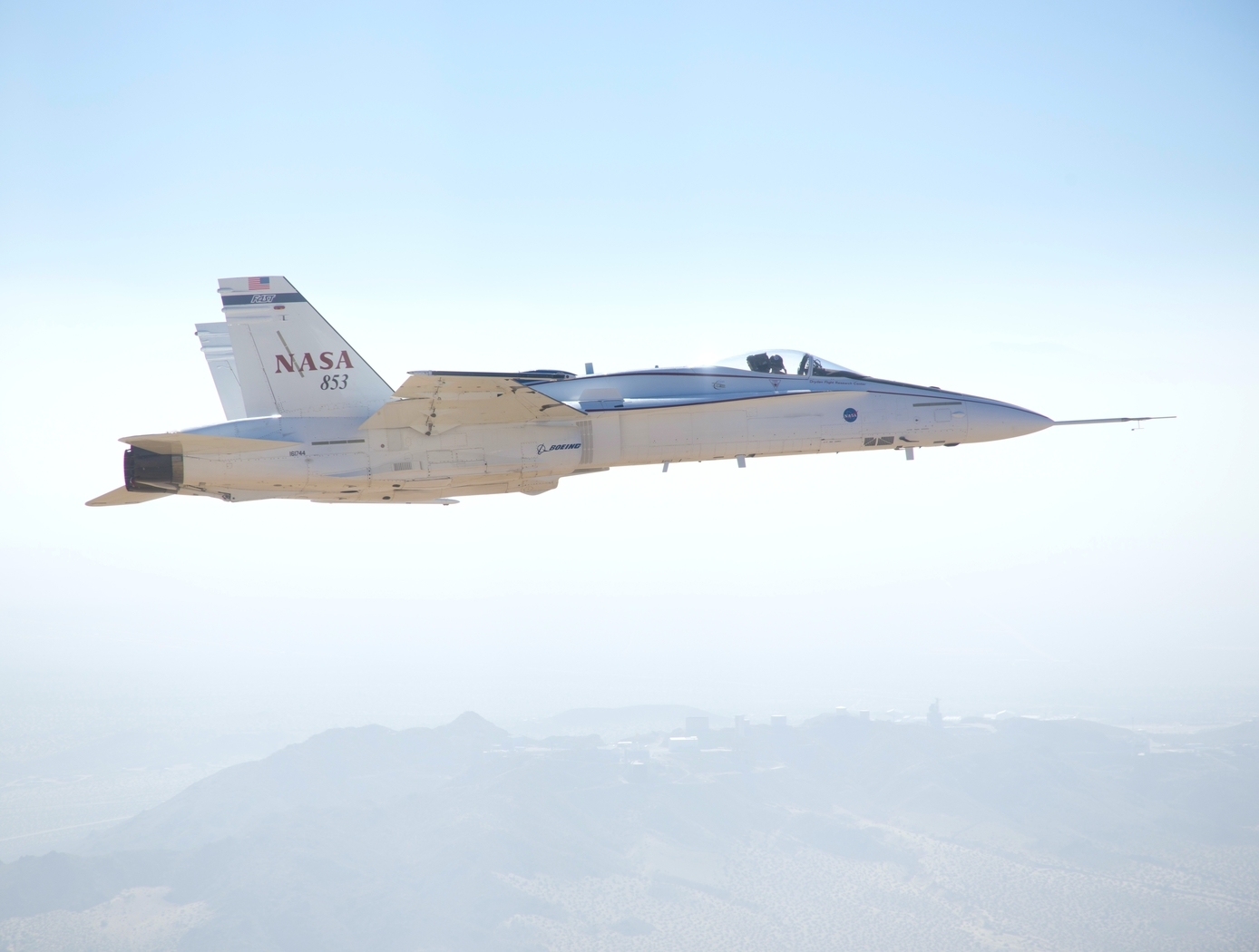
Although simple-hinged flaps represent optimal high-lift systems for reducing cruise drag, previous attempts to design flow control systems enabling such technology in transport aircraft have been unsuccessful. This is largely because such systems generally require a tradeoff between (a) the ability to achieve the required lift performance, and (b) possessing sufficiently low pneumatic power to enable feasible aircraft system integration (i.e., avoiding excess weight penalties associated with high pneumatic power). For example, electrically powered AFC systems (e.g., plasma actuators, synthetic jet actuators) have practical power requirements, but with limited control authority, making such systems ineffective for highly deflected flaps. On the other hand, circulation control systems can provide necessary lift for airfoils or wings with high flap deflections, but require too much pneumatic power for aircraft integration. NASA’s HELP AFC system represents a breakthrough in flow separation control technology – to efficiently achieve necessary lift performances while requiring low pneumatic power relative to alternative flow control techniques.
NASA’s HELP AFC system uses a unique two-row actuator approach comprised of upstream sweeping jet (SWJ) actuators and downstream discrete jets, which share the same air supply plenum. The upstream (row 1) SWJ actuators provide good spanwise flow-control coverage with relatively mass flow, effectively pre-conditioning the boundary layer such that the downstream (row 2) discrete jets achieve better flow control authority. The two row actuator system, working together, produce a total aerodynamic lift greater than the sum of each row acting individually. The result is a system that generates sufficient lift performance for simple-hinged flaps with pneumatic power requirements low enough to enable aircraft integration.
Mechanical and Fluid Systems
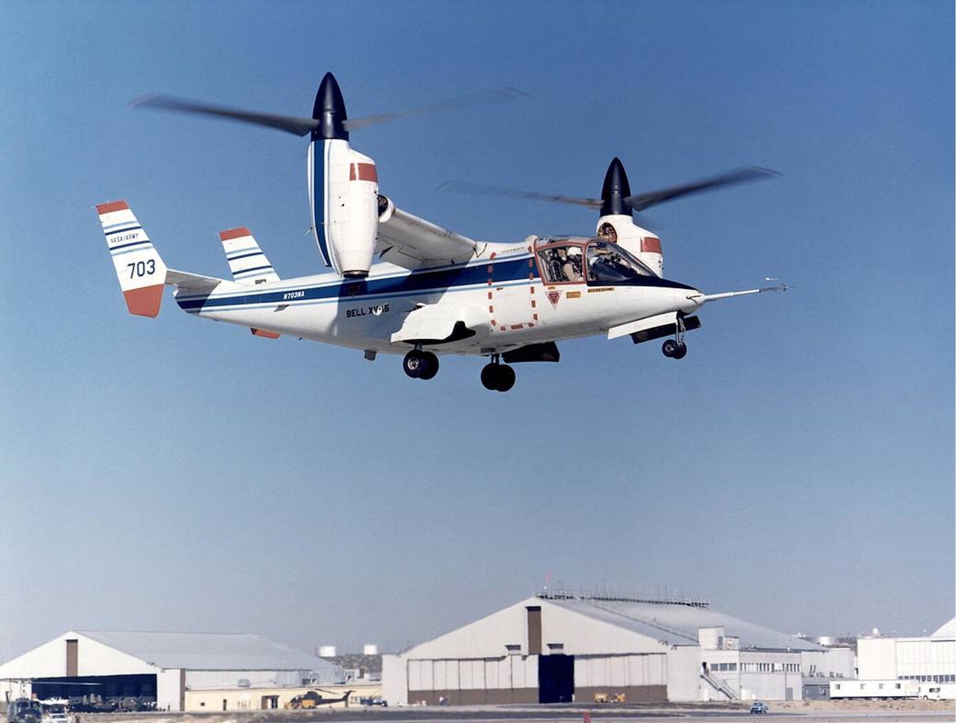
Improving VTOL Proprotor Stability
Proprotors on tiltrotor aircraft have complex aeroelastic properties, experiencing torsion, bending, and chord movement vibrational modes, in addition to whirl flutter dynamic instabilities. These dynamics can be stabilized by high-frequency swashplate adjustments to alter the incidence angle between the swashplate and the rotor shaft (cyclic control) and blade pitch (collective control). To make these high-speed adjustments while minimizing control inputs, generalized predictive control (GPC) algorithms predict future outputs based on previous system behavior. However, these algorithms are limited by the fact that tiltrotor systems can substantially change in orientation and airspeed during a normal flight regime, breaking system continuity for predictive modeling.
NASA’s Advanced GPC (AGPC) is a self-adaptive algorithm that overcomes these limitations by identifying system changes and adapting its predictive behavior as flight conditions change. If system vibration conditions deteriorate below a set threshold for a set time interval, the AGPC will incrementally update its model parameters to improve damping response. AGPC has shown significant performance enhancements over conventional GPC algorithms in comparative simulations based on an analytical model of NASA’s TiltRotor Aeroelastic Stability Testbed (TRAST). Research for Hardware-In-the-Loop testing and flight vehicle deployment is ongoing, and hover data show improved vibration reduction and stability performance using AGPC over other methods.
The example presented here is an application to tiltrotor aircraft for envelope expansion and vibration reduction. However, AGPC can be employed on many dynamic systems.
Aerospace
Aerospace Vehicle Entry Flightpath Control
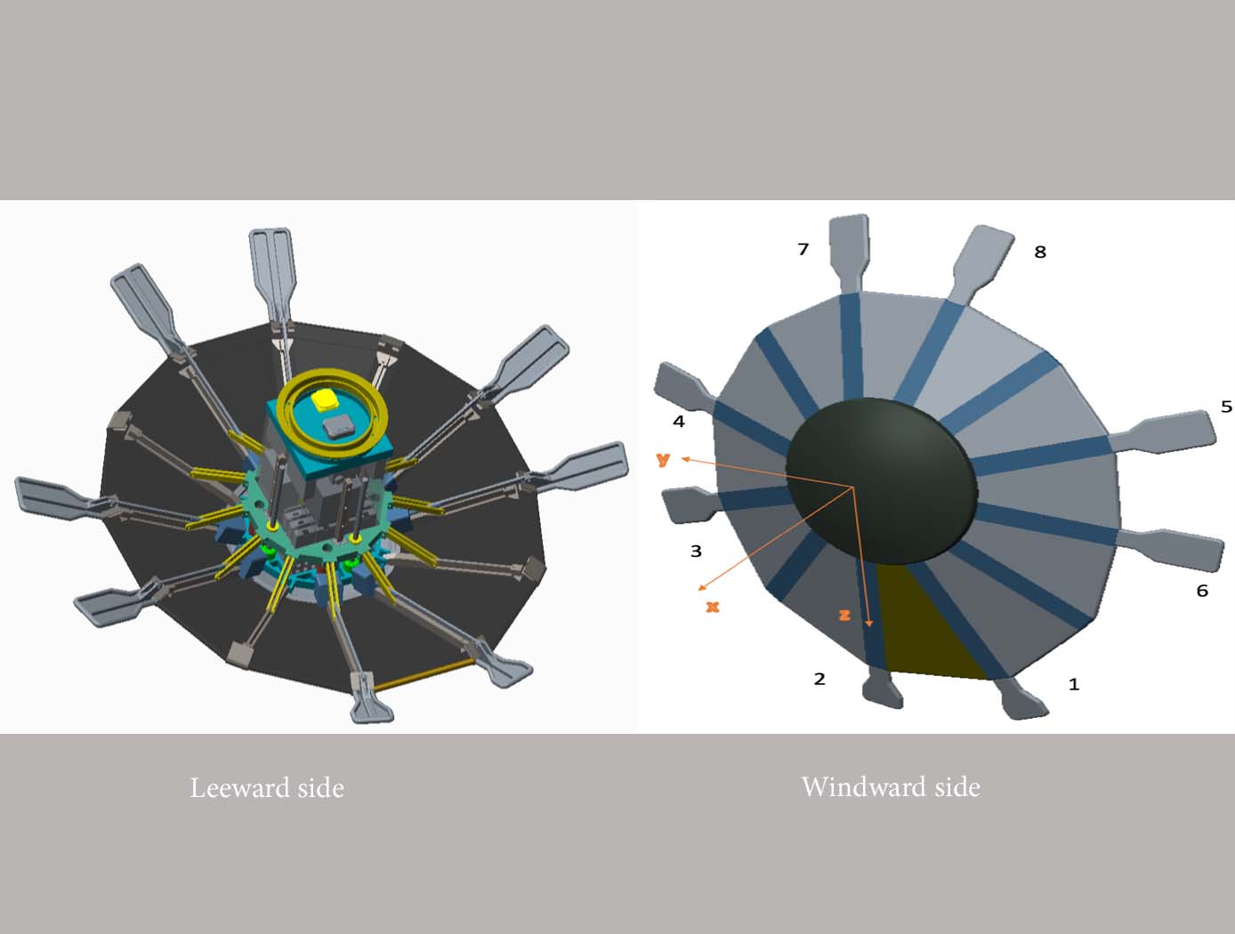
This novel flightpath control system exploits the dihedral effect to control the bank angle of the vehicle by modulating sideslip (Figure 1). Exploiting the dihedral effect, in combination with significant aerodynamic forces, enables faster bank accelerations than could be practically achieved through typical control strategies, enhancing vehicle maneuverability. This approach enables vehicle designs with fewer control actuators since roll-specific actuators are not required to regulate bank angle. The proposed control method has been studied with three actuator systems (figure below), Flaps Control System (FCS); Mass Movement Control System (MMCS); and Reaction Control System (RCS).
• FCS consists of a flap configuration with longitudinal flaps for independent pitch control, and lateral flaps generating yaw moments. The flaps are mounted to the shoulder of the vehicle’s deployable rib structure. Additionally, the flaps are commanded and controlled to rotate into or out of the flow. This creates changes in the vehicle’s aerodynamics to maneuver the vehicle without the use of thrusters.
• MMCS consists of moveable masses that are mounted to several ribs of the DEV heatshield, steering the vehicle by shifting the vehicle’s Center of Mass (CoM). Shifting the vehicle’s CoM adjusts the moment arms of the forces on the vehicle and changes the pitch and yaw moments to control the vehicle’s flightpath.
• RCS thrusters are mounted to four ribs of the open-back DEV heatshield structure to provide efficient bank angle control of the vehicle by changing the vehicle’s roll. Combining rib-mounted RCS thrusters with a Deployable Entry Vehicle (DEV) is expected to provide greater downmass capability than a rigid capsule sized for the same launch
aerospace
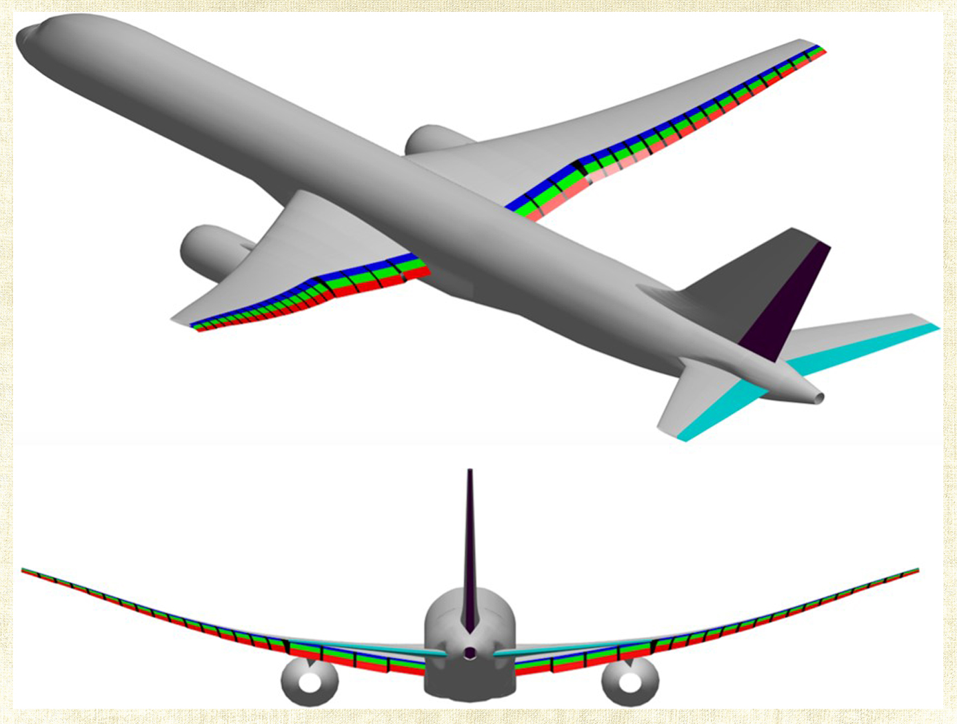
Multi-Objective Flight Control Optimization Framework
Composite materials are being used in aerospace design because of their high strength-to-weight ratio. On modern airplanes, composite wings offer a greater degree of aerodynamic efficiency due to weight savings, but at the same time introduce more structural flexibility than their aluminum counterparts. Under off-design flight conditions, changes in the wing shape due to structural flexibility cause the wing aerodynamics to be non-optimal. This effect could offset any weight saving benefits realized by the composite wings. Structural flexibility could also cause adverse interactions with flight control and structural vibration which can compromise aircraft stability, pilot handling qualities, and passenger ride quality. NASA Ames Research Center has developed a novel technology that employs a new multi-objective flight control optimization framework to achieve multiple control objectives simultaneously. This technology leverages the availability of distributed flight control surfaces in modern transports. The multi-objective flight control technology comprises the following objectives all acting in a synergistic manner: 1) traditional stability augmentation and pilot command-following flight control, 2) drag minimization, 3) aeroelastic mode suppression, 4) gust load alleviation, and 5) maneuver load alleviation. Each of these objectives can be a major control system design in its own right. Thus, the multi-objective flight control technology can effectively manage the complex interactions of the individual single-objective flight control system design and take into account multiple competing requirements to achieve optimal flight control solutions that have the best compromise for these requirements. In addition, a real- time drag minimization control strategy is included in the guidance loop. This feature utilizes system identification methods to estimate aerodynamic parameters for the on-line optimization. The aerodynamic parameters are also used in the multi-objective flight control for drag minimization and maneuver/ gust load alleviation control.
mechanical and fluid systems
Tension Element Vibration Damping
NASAs Tension Element Vibration Damping technology presents a novel method of managing the dynamic behavior of structures by capturing the vibrational displacement of the structure via a connecting link and using this motion to drive a resistive element. The resistive element then provides a force feedback that manages the dynamic behavior of the total system or structure. The damping force feedback can be a tensile or compressive force, or both. Purely tensile force has advantages for packaging and connection alignment flexibility while combined tensile/compression forces have the advantage of providing damping over a complete vibratory cycle.
This innovation can be readily applied to existing structures and incorporated into any given design as the connecting element is easily affixed to displacing points within the structure and the resistive element to be located in available space or a convenient location. The resistive element can be supplied by any one of either hydraulic, pneumatic or magnetic forces. As such the innovation can provide a wide range of damping forces, a linear damping function and/or an extended dynamic range of attenuation, providing broad flexibility in configuration size and functional applicability.
NASA-built prototypes have been shown to be highly effective on a 170-foot long wind turbine blade in test beds at the University of Maine.
Mechanical and Fluid Systems
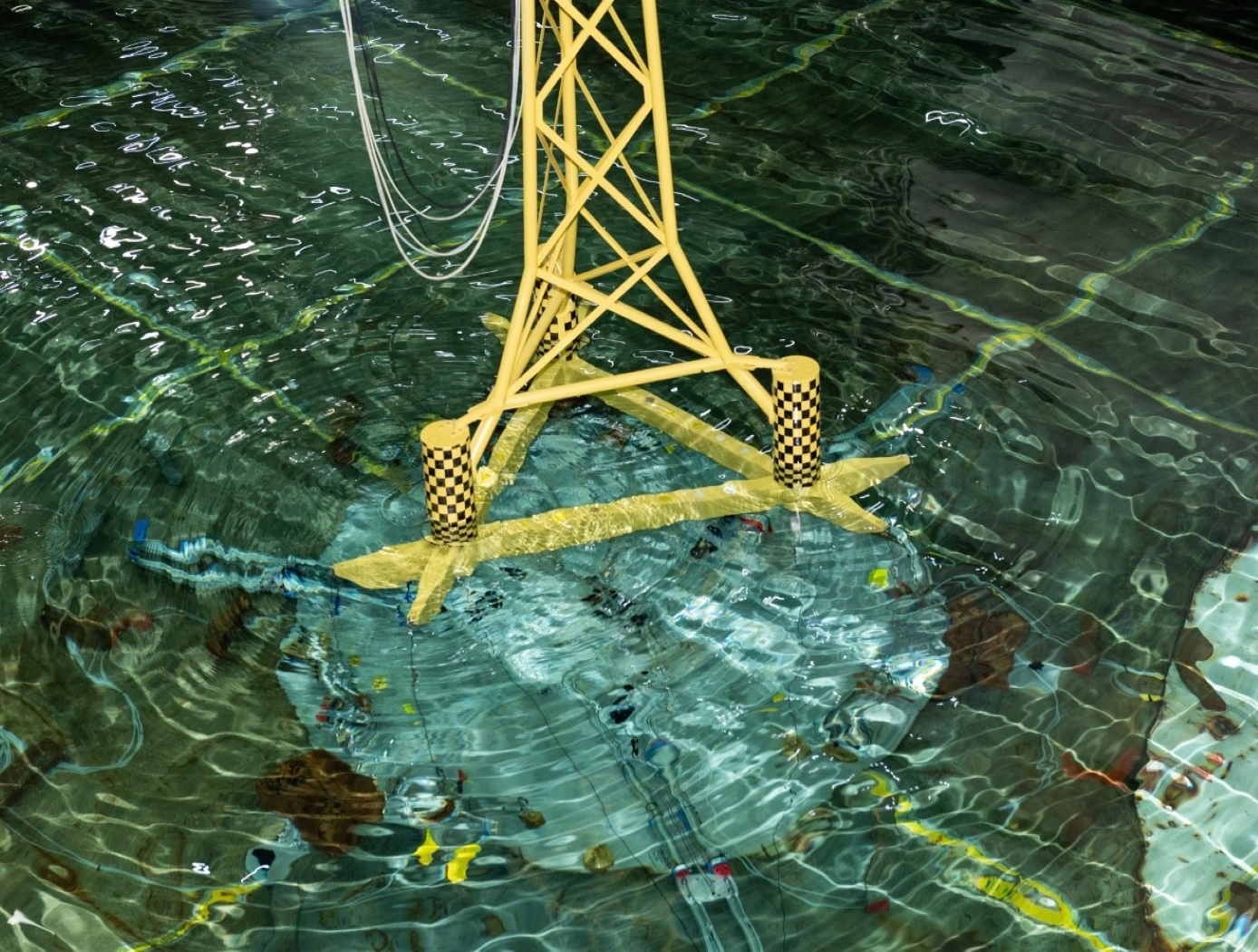
Ocean Platform Motion Control
The NASA innovation leverages existing ballast fluid of a maritime structure to proactively mitigate undesirable resonant response characteristics of the platform or vessel. Essentially, this innovation couples water ballast as a functional working mass to the dynamic motion of a floating structure in order to provide passive motion management of the primary structure.
The system can be implemented pre-design or post manufacture. The systems are simple and are easily manufactured, transported, and implemented onto a primary structure.
The NASA technology has been designed (patents applied for) for a range of platform designs and can be further customized depending on the final application requirements. Prototypes have been built and tested in a wind-wave tank test bed at the University of Maine.
Aerospace
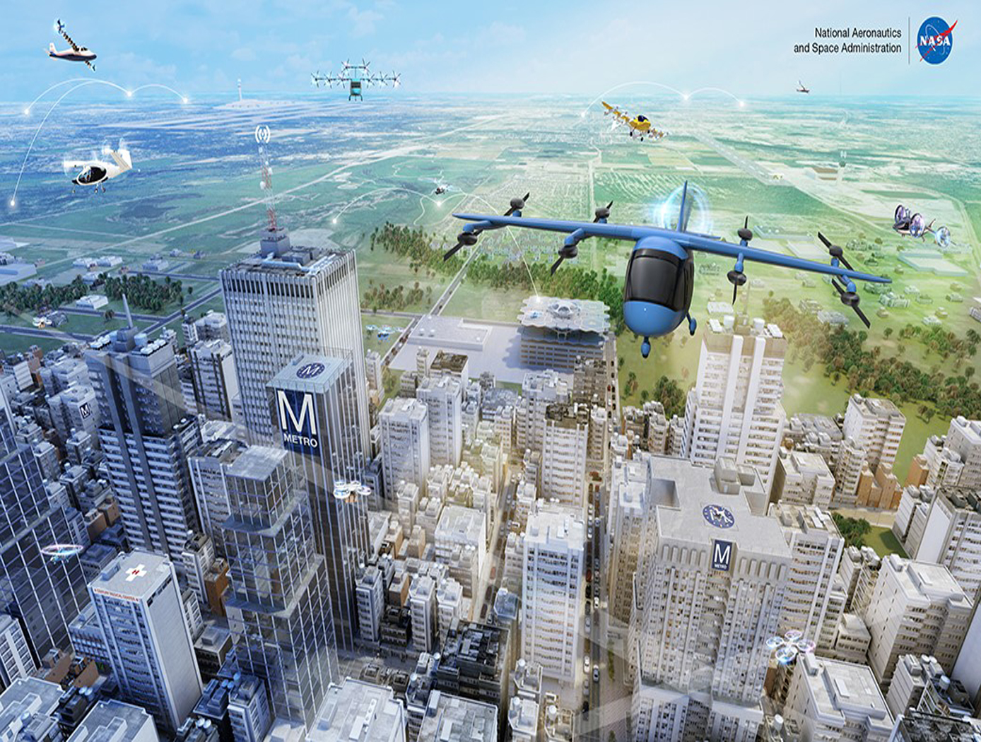
Active Turbulence Suppression System for Electric Vertical Take-Off and Landing (eVTOL) vehicles
The Active Turbulence Suppression (ATS) system for electric Vertical Take-Off and Landing (eVTOL) vehicles employ existing lifting propellers to dampen instabilities during flight, such as Dutch-roll oscillations and other gust-induced oscillations. When a roll angle of an eVTOL aircraft has deviated or is about to deviate from a current stable aircraft state to an undesirable, unstable, and oscillating aircraft state, the ATS system queries a turbulence suppression database that stores a set of propeller speed profiles for mitigation a deviation of a given roll angle for a particular aircraft with specified propellers. Using this data, the eVTOL flight controller adjusts the speed of the propellers for a certain duration of time, according to the propeller speed profiles for mitigating the deviation. In models of aircraft with adjustable propeller angles, the database includes blade angle profiles for mitigating the effects of turbulent conditions. Timing and rate of propeller activation can be pre-computed using higher order computational modeling performed with NASA’s super computing resources. Because the data is pre-computed, the use of the ATS system onboard does not require significant computing resources to implement on eVTOL vehicles. The technology, a mechanism by which existing eVTOL propellers are leveraged to suppress gust-induced oscillations enables a safe and comfortable passenger experience at low-cost and without added hardware.
aerospace

Improved Fixed-Wing Gust Load Alleviation Device
Gust loads may have detrimental impacts on flight including increased structural and aerodynamic loads, structural deformation, and decreased flight dynamic performance. This technology has been demonstrated to improve current gust load alleviation by use of a trailing-edge, free-floating surface control with a mass balance. Immediately upon impact, the inertial response of the mass balance shifts the center of gravity in front of the hinge line to develop an opposing aerodynamic force alleviating the load felt by the wing. This passive gust alleviation control covering 33% of the span of a cantilever wing was tested in NASA Langleys low speed wind tunnel and found to reduce wing response by 30%.
While ongoing experimental work with new laser sensing technologies is predicted to similarly reduce gust load, simplicity of design of the present invention may be advantageous for certification processes. Additionally, this passive technology may provide further gust alleviation upon extending the use of the control to the entire trailing edge of the wing or upon incorporation with current active gust alleviation systems.
Importantly, the technology can be easily incorporated into to the build of nearly all fixed wing aircrafts and pilot control can be maintained through a secondary trim tab. Though challenging to retrofit, passive gust alleviation could enable use of thinner, more efficient wings in new plane design.

