Search
Manufacturing

Automated Fabric Circuit and Antenna Fabrication
Modern production of e-textiles utilizes an embroidery technique called “e-broidery” that directly stitches circuit patterns with conductive thread onto textiles. This automated manufacturing process combines steps of e-broidery and milling to expand the application of e-textiles to high-current and high-speed uses. Manufacturing begins with two layouts of the desired conductive pattern. After assembling the layers of conductive and nonconductive materials, e-broidery is performed with the second layout and nonconductive thread to secure the layers together and designate the pattern for the conductive material. The secured assembly is transferred to an automated milling or laser cutting machine, which cuts the desired conductive pattern and releases the unneeded portions of the conductive material. The resulting e-textiles are tightly woven together, providing higher surface conductivity and impedance control. Initial comparison tests assessing the performance of fabric-based spiral antennas developed with this method, compared to conventional antennas, indicated no loss in performance across multiple metrics, including voltage standing wave ratio (VSWR), radiation pattern, and axial ratio performance.
The Method and Apparatus for Fabric Circuits and Antennas is a technology readiness level (TRL) 6 (system/subsystem prototype demonstration in a relevant environment). The innovation is now available for your company to license. Please note that NASA does not manufacture products itself for commercial sale.
Materials and Coatings

Advanced Materials for Electronics Insulation
Many researchers have attempted to use polymer-ceramic composites to improve the thermal and dielectric performance of polymer insulation for high voltage, high temperature electronics. However, using composite materials has been challenging due to manufacturing issues like incomplete mixing, inhomogeneous properties, and void formation. Here, NASA has developed a method of preparing and extruding polymer-ceramic composites that results in high-quality, flexible composite ribbons.
To achieve this, pellets of a thermoplastic (e.g., polyphenylsulfone or PPSU) are coated with an additive then mixed with particles of a ceramic (e.g., boron nitride or BN) as shown in the image below. After mixing the coated polymer with the ceramic particles, the blended material was processed into ribbons or films by twin-screw extrusion. The resulting ribbons are highly flexible, well-mixed, and void free, enabled by the coated additive and by using a particle mixture of micronized BN and nanoparticles of hexagonal BN (hBN).
The polymer-ceramic composite showed tunable dielectric and thermal properties depending on the exact processing method and composite makeup. Compared to the base polymer material, the composite ribbons showed comparable or improved dielectric properties and enhanced thermal conductivity, allowing the composite to be used as electrical insulation in high-power, high-temperature conditions.
The related patent is now available to license. Please note that NASA does not manufacturer products itself for commercial sale.
aerospace
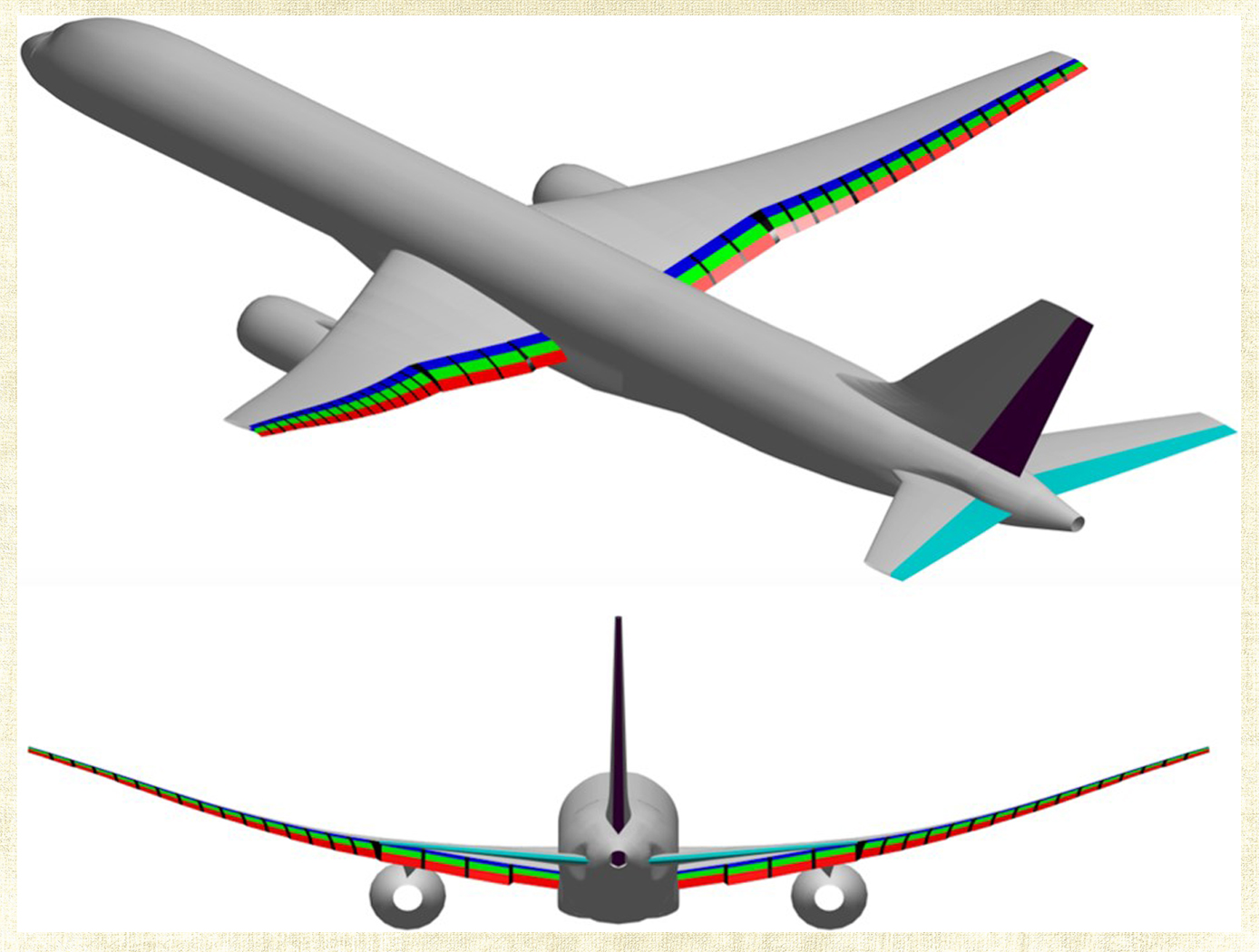
Multi-Objective Flight Control Optimization Framework
Composite materials are being used in aerospace design because of their high strength-to-weight ratio. On modern airplanes, composite wings offer a greater degree of aerodynamic efficiency due to weight savings, but at the same time introduce more structural flexibility than their aluminum counterparts. Under off-design flight conditions, changes in the wing shape due to structural flexibility cause the wing aerodynamics to be non-optimal. This effect could offset any weight saving benefits realized by the composite wings. Structural flexibility could also cause adverse interactions with flight control and structural vibration which can compromise aircraft stability, pilot handling qualities, and passenger ride quality. NASA Ames Research Center has developed a novel technology that employs a new multi-objective flight control optimization framework to achieve multiple control objectives simultaneously. This technology leverages the availability of distributed flight control surfaces in modern transports. The multi-objective flight control technology comprises the following objectives all acting in a synergistic manner: 1) traditional stability augmentation and pilot command-following flight control, 2) drag minimization, 3) aeroelastic mode suppression, 4) gust load alleviation, and 5) maneuver load alleviation. Each of these objectives can be a major control system design in its own right. Thus, the multi-objective flight control technology can effectively manage the complex interactions of the individual single-objective flight control system design and take into account multiple competing requirements to achieve optimal flight control solutions that have the best compromise for these requirements. In addition, a real- time drag minimization control strategy is included in the guidance loop. This feature utilizes system identification methods to estimate aerodynamic parameters for the on-line optimization. The aerodynamic parameters are also used in the multi-objective flight control for drag minimization and maneuver/ gust load alleviation control.
Mechanical and Fluid Systems

Multi-Link Spherical Joint
The Multi-Link Spherical Joint developed at NASA Johnson Space Center provides a substantial improvement over typical joints in which only two linearly actuated links move independently from one another. It was determined that the rotation point of a trussed link needed to be collocated at a shared point in space for maximum articulation. If not allowed separate rotation, the line of action through a universal joint and hinge acts effectively as another linkage. This leads to a much more complex and uncontrollable structure, especially when considering multiple dimensions.
Comprising the Multi-Link Spherical Joint, a spherical shell encases the cupped ends of each six possible attachments and allows each of those attachments to be independently controlled and rotated without inhibiting the motion of the others. To do this, each link is precisely limited to 15 degrees of rotation off the link centerline, thus allowing a total of 30 degrees of rotation for each link. The shell-and-cup structure can handle the loads of linear actuators that may be used to control and vary the geometry of a truss system utilizing the new joint technology. The calculated operating load that the truss system must handle can be used to scale the size of the joint, further allowing customization of any potential truss system. Additionally, the incorporated linear actuators can be controlled and powered by wiring routed through the joint without putting undo stress on the wires during operation. Accordingly, this innovative joint technology enables more efficient deployment and precise operation of articulating structures.
The Multi-Link Spherical Joint is at technology readiness level (TRL) 4 (component and/or breadboard validation in laboratory environment) and is available for patent licensing. Please note that NASA does not manufacture products itself for commercial sale.
Robotics Automation and Control
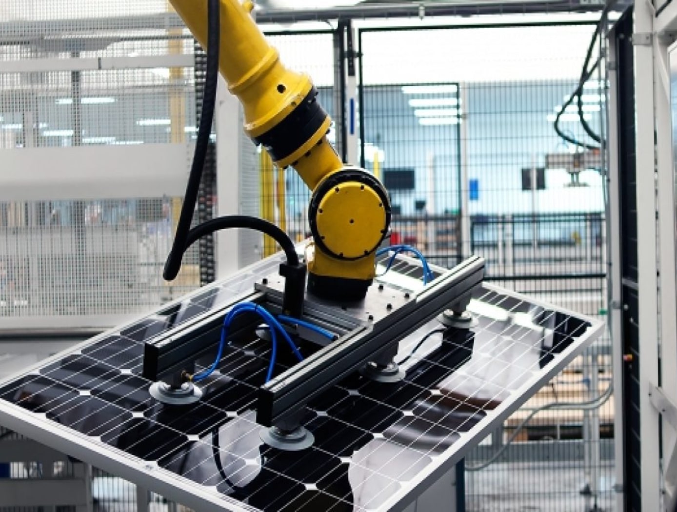
Robotic Assembly of Photovoltaic Arrays
NASA researchers have developed the PAPA technology to increase the efficiency of the thin-film solar array assembly process, significantly decreasing assembly time and labor costs associated with manufacturing large scale solar arrays. Traditional solar cell assembly is a labor intensive, multi-step, time-consuming process. This manual assembly will not be possible in a space environment. To enable solar array assembly in space, PAPA leverages robotic automation to distill the traditional assembly method into four fully automated steps: applying adhesive to block substrate, placing the solar cells using a vacuum tool attached to a universal robotic arm, printing the interconnects and buses to connect the cells, and applying a protective cover.
The PAPA technology is compatible with a variety of thin-film solar cells, including 3D printed cells (essential for future in-space manufacturing of arrays) and terrestrial manufacturing methods. As solar cell technologies mature, PAPA will be able to incorporate advancements into the paneling process. NASA researchers have begun to employ PAPA solar array fabrication and estimate savings of $300-$400/watt. For extraterrestrial assembly of solar panels the size of a football field or larger, PAPA could result in savings of approximately $500 million; a substantial cost savings driven by standardization and efficiency in the solar array assembly process. By demonstrating increases in assembly efficiency, time and cost savings, and passing multiple environmental exposure tests, the PAPA lab protype has completed the final phases of technology development and is ready for scale-up and commercialization.
electrical and electronics
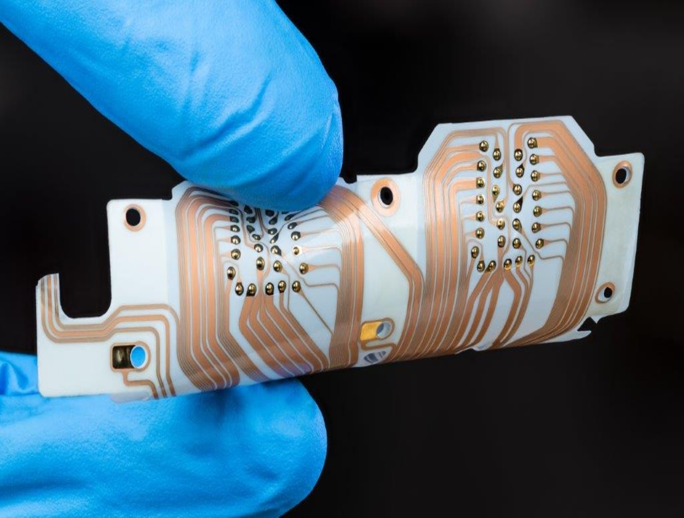
Printable IoT sensor development platform
Advances in additive manufacturing have enabled development of printable electronic sensor elements that can be deposited onto flexible substrates. To benchmark performance of printed sensors against the state of the art, NASA developed a low power flexible sensor platform. The platform integrates the following key components and features:
-Flexible substrate: DuPont Kapton allows bending around cylindrical surfaces as small as in diameter.
-Embedded microcontroller: Cypress CY8C4248 LQI-BL583 Arm Cortex M0 processor with BLE wireless controller, max frequency 48 MHz. Supports low power modes of operation, capacitive sensing support, and a single-channel 12-bit AD converter.
-Commercial sensor suite: Bosch BNO080 inertial sensor; Bosch BME280 humidity, pressure, and temperature sensor; AMS CCS811 air quality sensor (VOCs and CO2).
-Prototyping area for custom-printed sensors: 1) thermistor, uses carbon-based PTC resistor paste DuPont2792; 2) capacitive humidity sensor using a NASA-developed dielectric ink.
NASA researchers have used the platform to study performance of the printed capacitive humidity sensor. The 2x4 mm co-doped barium titanate sensing element is highly sensitive to water vapor and performs as an unobtrusive breathing monitor, sensitive to breath at distances of up to 20 cm. Average change of sensor capacitance at a distance of 7.5 cm was observed to be 6.23.5 pF.
Materials and Coatings

Flexible Phenolic Intermingled Carbon Ablators (PICA-Flex)
Flexible PICAs combine both carbon and phenolic fiber constituents during a felting process rather than introducing a phenolic through infusion processes that also uses harsh chemicals. MERINO PICA-Flex materials drastically reduces integration complexities when compared to traditional phenolic infused rigid tiles, and can eliminate the costly and time intensive phenolic infusion process, resulting in a thermal protection system (TPS) material more akin to a “blanket” than a rigid TPS. PICA-Flex encompasses a range of configurations, including a dual layer PICA-Flex material with a higher density outer layer(s) to minimize recession, a lower density PICA-Flex material with applicability to aftbody TPS, and a single piece PICA-Flex forebody. PICA-Flex is fabricated by combining by intermingling both carbon and phenolic fiber constituents during a needle punch felting process during which the fibers are made into battings, and the battings are needled together layer-by-layer to build up thickness.
Aerospace
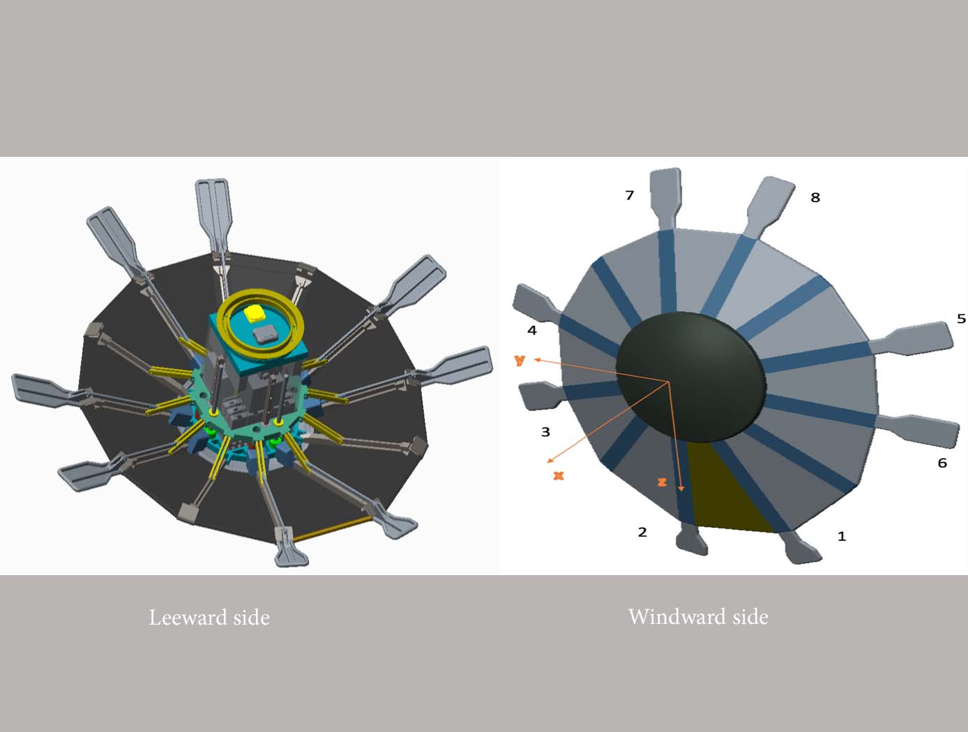
Aerospace Vehicle Entry Flightpath Control
This novel flightpath control system exploits the dihedral effect to control the bank angle of the vehicle by modulating sideslip (Figure 1). Exploiting the dihedral effect, in combination with significant aerodynamic forces, enables faster bank accelerations than could be practically achieved through typical control strategies, enhancing vehicle maneuverability. This approach enables vehicle designs with fewer control actuators since roll-specific actuators are not required to regulate bank angle. The proposed control method has been studied with three actuator systems (figure below), Flaps Control System (FCS); Mass Movement Control System (MMCS); and Reaction Control System (RCS).
• FCS consists of a flap configuration with longitudinal flaps for independent pitch control, and lateral flaps generating yaw moments. The flaps are mounted to the shoulder of the vehicle’s deployable rib structure. Additionally, the flaps are commanded and controlled to rotate into or out of the flow. This creates changes in the vehicle’s aerodynamics to maneuver the vehicle without the use of thrusters.
• MMCS consists of moveable masses that are mounted to several ribs of the DEV heatshield, steering the vehicle by shifting the vehicle’s Center of Mass (CoM). Shifting the vehicle’s CoM adjusts the moment arms of the forces on the vehicle and changes the pitch and yaw moments to control the vehicle’s flightpath.
• RCS thrusters are mounted to four ribs of the open-back DEV heatshield structure to provide efficient bank angle control of the vehicle by changing the vehicle’s roll. Combining rib-mounted RCS thrusters with a Deployable Entry Vehicle (DEV) is expected to provide greater downmass capability than a rigid capsule sized for the same launch

