Search
manufacturing
Improving Formability of Al-Li Alloys
Via this NASA innovation, a product is first heated to a temperature within the range of 204 to 343 degrees C for an extended soak of up to 16 hours. The product is then slowly heated to a second temperature within the range of 371 to 482 degrees C for a second soak of up to 12 hours. Finally, the product is slowly cooled to a final soak temperature of 204 to 343 degrees C before cooling to room temperature. The product so treated will exhibit greatly improved formability.
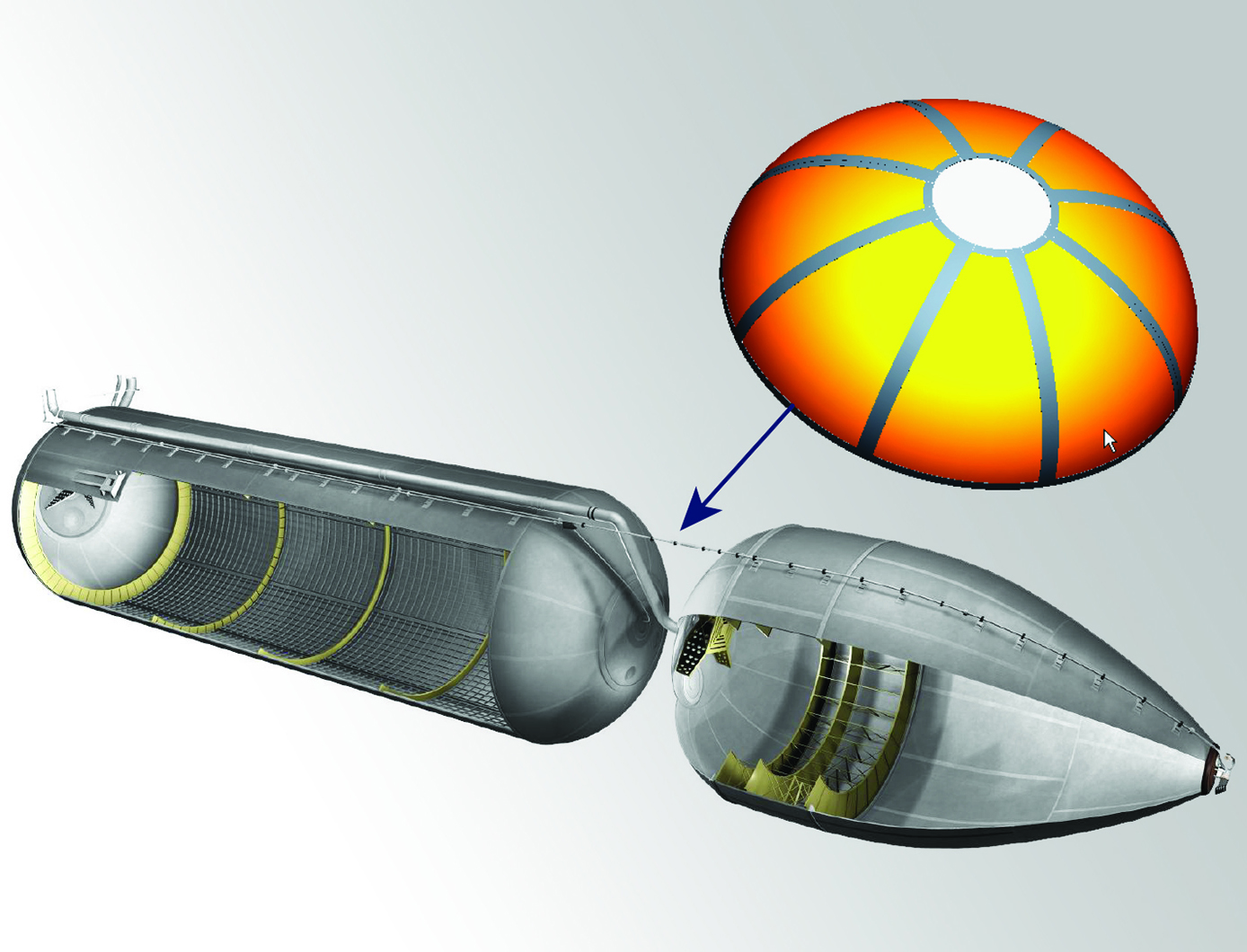
To date, the low formability issue has limited the use of lightweight Al-Li alloys for large rocket fuel tank dome applications. Manufacturing a dome by stretch forming typically requires multiple panels as well as multiple welding and inspection steps to assemble these panels into a full-scale fuel tank dome. Complex tensile and bending stresses induced during the stretch forming operations of Al-Li alloys have resulted in high rates of failure for this process. To spin form a large rocket dome, the spin blank must be prepared by joining smaller plates together using friction stir welding. However, friction stir welding produces a distinct metallurgical structure inside and around the friction stir weld that makes it very susceptible to cracking during spin forming.
materials and coatings
Multi-layered Self-healing Material System for Impact Mitigation
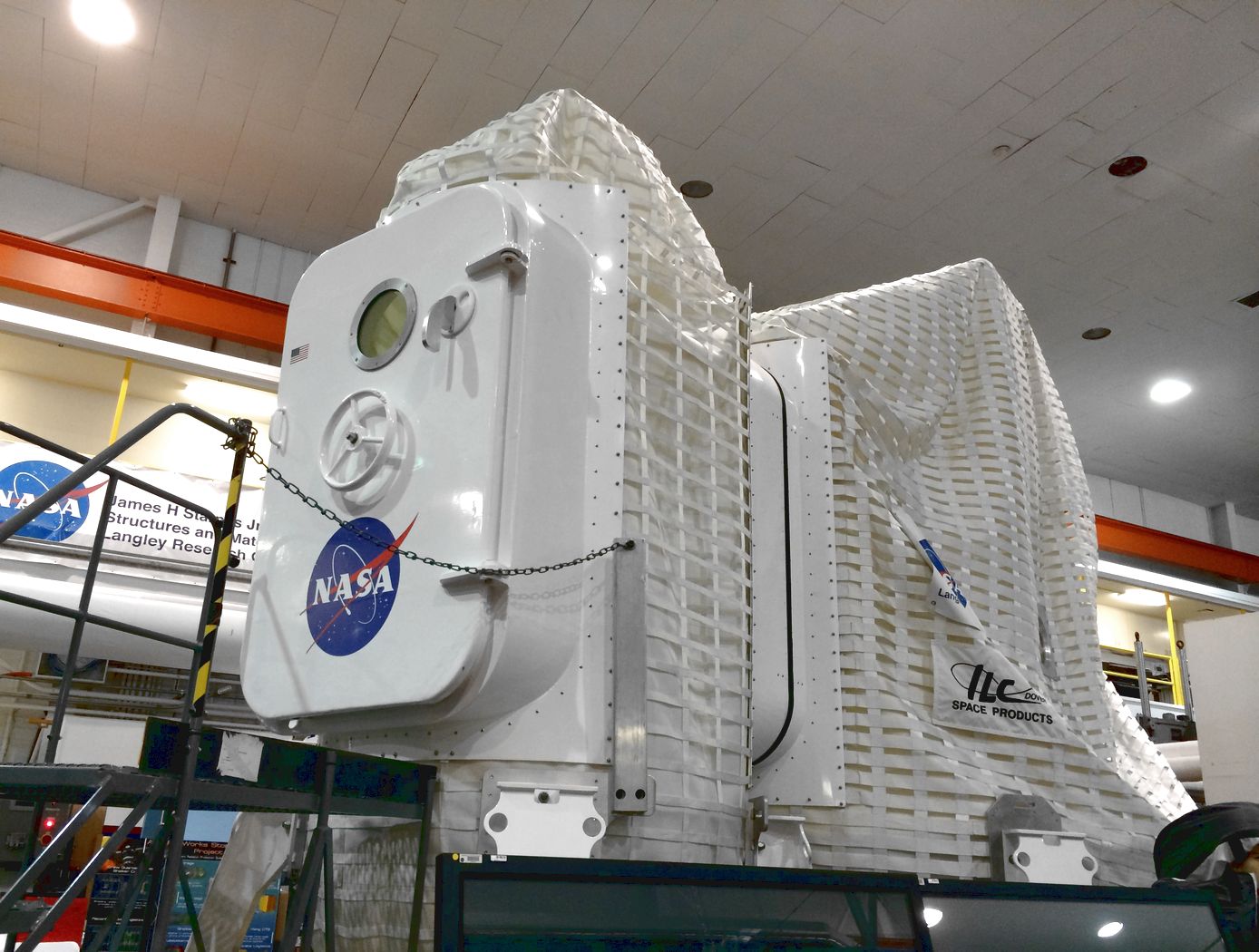
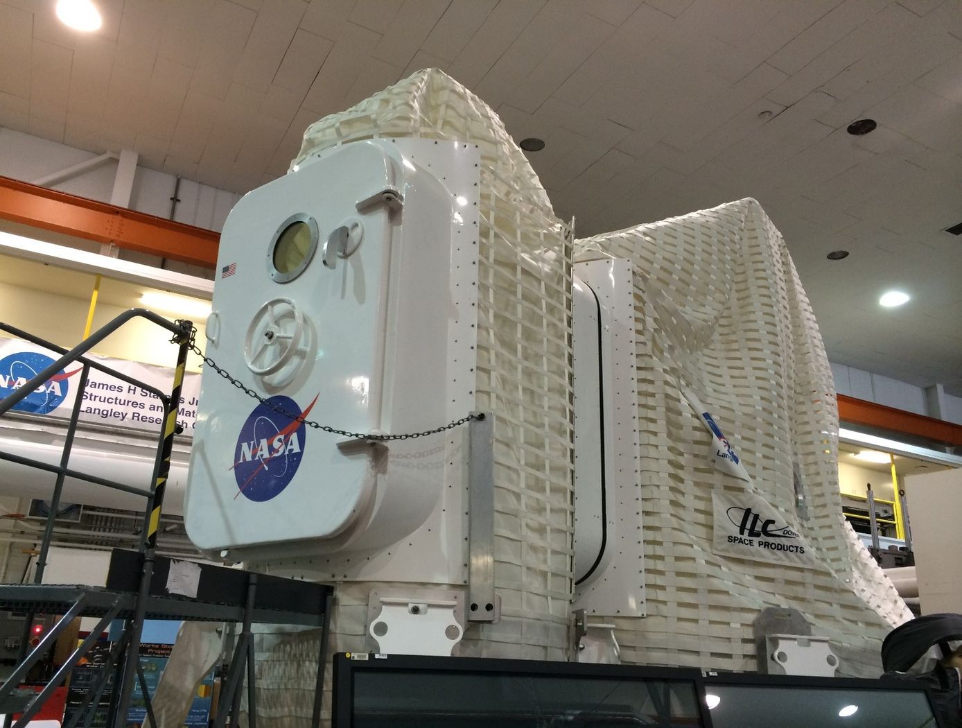
This innovation utilizes a tri-layered structure, comprised of solid plastic front and back layers sandwiching a viscous, reactive liquid middle layer. Combined, this system provides rapid self-healing following high velocity ballistic penetrations. Self-healing in the front and back layers occurs when the puncture event creates a melt state in the polymer materials and the materials melt elasticity snaps back and closes the hole. The viscous middle layer augments the self-healing properties of the other layers by flowing into the gap created by a ballistic puncture and concurrently solidifying due to the presence of oxygen. Thus, this innovation has two tiers of self-healing: a puncture-healing mechanism triggered by the projectile and a second mechanism triggered by the presence of oxygen.
mechanical and fluid systems

Healable Carbon Fiber Reinforced Composites
A composite fabrication process cycle was developed from composite precursor materials developed at LaRC to fabricate composite laminates. The precursor material is a pre-impregnated unidirectional carbon fiber preform, or prepreg. In the pre-pregging process, the high strength, structural reinforcing carbon fiber is wetted by a solution containing a self-healing polymer. The resulting material is of aerospace quality and exhibits a significant decrease of internal damage following impacts tests (using ASTM D 7137 standard).
Materials and Coatings
Mechanoresponsive Healing Polymers
The method chemically introduces mechanically sensitive chemical groups into the structure of a resin. By introducing mechanoresponsive functional groups to a polymer, it is possible to induce self-healing through the transformation of such chemical groups to where mechanical properties of a structure are almost completely restored. The forces imparted by a damage event can therefore be used to enable healing or repair of the structure.
sensors
Low-Profile Wireless Sensor
The low-profile sensor is configured with a spiral electrical trace on flexible substrate. In typical inductor designs, the space between traces is designed to minimize parasitic conductance to reduce the impact of the capacitance to neighboring electronics. In the low-profile sensor, however, greater capacitance is desired to allow the operation of an inductor-capacitor circuit. This allows the traces to be closer together, decreasing the
overall size of the spiral trace.
The sensor receives a signal from the accompanying magnetic field data acquisition system. Once electrically active, the sensor produces its own harmonic magnetic field as the inductor stores and releases magnetic energy. The antenna of the measurement acquisition system is switched from a transmitting to a receiving mode to acquire the magnetic-field response of the sensor. The magnetic-field response attributes of frequency, amplitude, and bandwidth of the inductor correspond to the physical property states measured by the sensor. The received response is correlated to calibration data to determine the physical property measurement. When multiple sensors are inductively coupled, the data acquisition system needs to activate and read
only one sensor to obtain measurement data from all of them.
Sensors

Optical Mass Sensor for Multi-Phase Flows
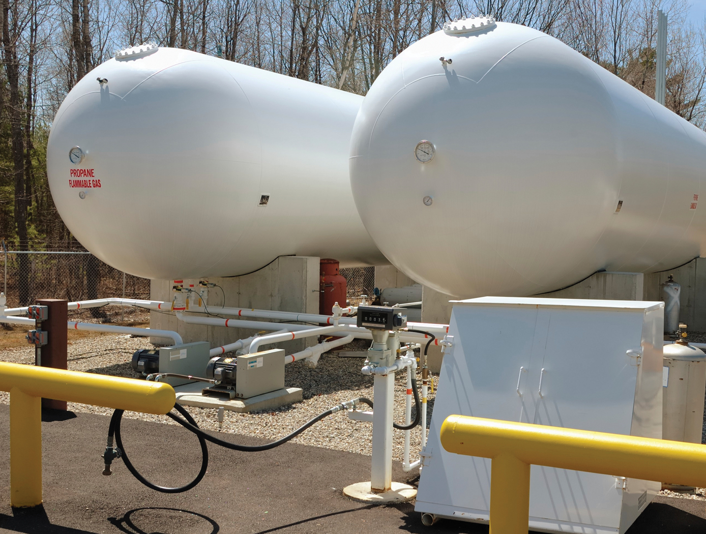
Unlike commercial turbine and Venturi-type sensors, which are flow intrusive and prone to high error rates, NASA's new flow sensor technology uses an optical technique to precisely measure the physical characteristics of a liquid flowing within a pipe. It generates a reading of the flows density, which provides a highly accurate mass flow measurement when combined with flow velocity data from a second optical sensor.
NASA's sensor technology provides both a void fraction measurement, which is a measurement of the instantaneous gas/liquid percentage of a static volume and a quality measurement, which is the fraction of flow that is vapor as part of a total mass flow. It also provides a direct measurement of the gas/liquid concentration within the flow, making it suited for real-time measurement of multi-phase flows.
The technology was originally developed to accurately determine the flow rates and tank levels of multi-phase cryogenic fuels used on various NASA vehicles including the Space Shuttle and in ground-based propulsion testing. It can also be used for a wide range of gas/liquid ratios, flows with complex cross sectional profiles, flows containing bubbles or quasi-solids, and essentially any liquid, gas, or multi-phase flow that can be optically characterized. Because it is insensitive to position, the new technology also has potential for use in zero-gravity tank level sensors.
sensors
Fluid Measurement Sensor
The fluid measurement sensor is configured with a spiral electrical trace on flexible substrate. The sensor receives a signal from the accompanying magnetic field data acquisition system. Once electrically active, the sensor produces its own harmonic magnetic field as the inductor stores and releases magnetic energy. The antenna of the measurement acquisition system is switched from transmitting to receiving mode to acquire the magnetic-field response of the sensor. The magnetic-field response attributes of frequency, amplitude, and bandwidth of the inductor correspond to the physical property states measured by the sensor. The received response is correlated to calibrated data to determine the physical property measurement. When multiple sensors are inductively coupled, the data acquisition system only needs to activate and read one sensor to obtain measurement data from all of them.
Fluid level measurement occurs in several ways. In the immersion method, the capacitance of the sensor circuit changes as it is immersed in fluid, thus changing the frequency response as the fluid level rises or falls. Fluid level can also be measured from the outside of a non-conductive container. The response frequency from the sensor is dependent upon the inductance of the container plus the combination of fluid and air inside it, which corresponds to the level of liquid inside the container. Roll and pitch are measured by using three or more sensors in a container. With any given orientation, each sensor will detect a different fluid level, thus providing the basis for calculating the fluid angle. Volume can be measured in the same way, using the angle
levels detected by the sensors and the geometric characteristics of the container to perform the volume calculation.
sensors
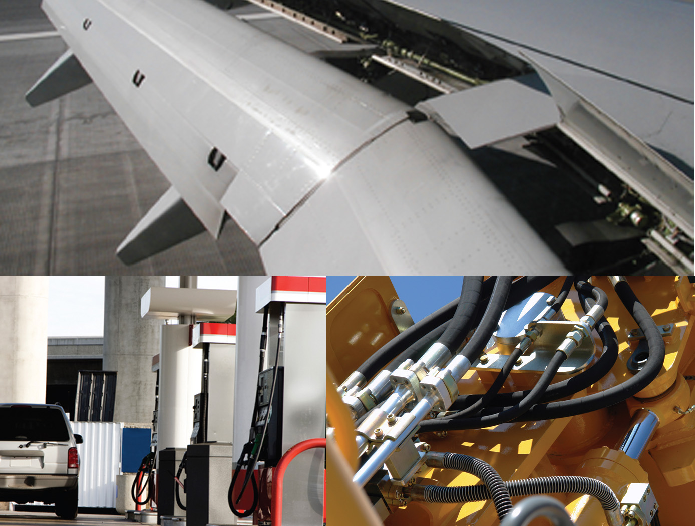
Highly Accurate Level Sensor
The FAA and Aircraft Industry recognize the need to reduce fuel tank explosion risk
by eliminating ignition sources and changing fuel tank design and maintenance.
This technology can be utilized to wirelessly sense the level of fuel in aircrafts, thus
mitigating risk of inadvertent electrical failures and sparks. NO wires enter the fuel
tank and the radio frequency transponder typically requires 10 milliwatts of power or
less.
The technology can be used for dielectric tanks, by simply applying the sensors to the
tank surface (as pictured). Through certain techniques the technology can be applied
on metal tanks with no wires entering the tank from the outside.
Currently, there are more than 20,910 jet aircraft in service. This presents a large
market opportunity for retrofitting this technology onto existing airplane fuel tanks
Rapidly evolving aviation services are expected to spur worldwide requirement for
36,770 new jet aircraft by 2033. This presents a growing market for new installations.
materials and coatings

Enhanced Software Suite Maximizes Non-Destructive Evaluation (NDE) Methods
This technology provides comprehensive, detailed, and accurate NDE detection and characterization of subsurface defects in composites and some metallic hardware. This complete software suite normalizes and calibrates the data, which provides more stable measurements and reduces the occurrence of errors due to the operator and to camera variability.
When using flash IR thermography to evaluate materials, variations in the thermal diffusivity of the material manifest themselves as anomalies in the IR image of the test surface. Post-processing of this raw IR camera data provides highly detailed analysis of the size and characterization of anomalies. The newly incorporated Transient and Lock-In Thermography methods allow the analysis of thicker material and with better flaw resolution than Flash Thermography alone.
The peak contrast and peak contrast time profiles generated through this analysis provide quantitative interpretation of the images, including detailed information about the size and shape of the anomalies. The persistence energy and persistence time profiles provide highly sensitive data for detected anomalies. Peak contrast, peak time, persistence time, and persistence energy measurements also enable monitoring for flaw growth and signal response to flaw size analysis.
This technology is at a technology readiness level (TRL) of 7 (system prototype demonstration in an operational environment), and the innovation is now available for your company to license. Please note that NASA does not manufacture products itself for commercial sale.
sensors

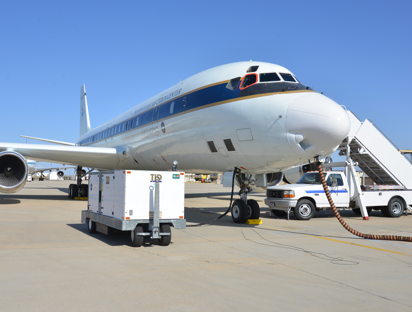
Streamlined Liquid Level Sensing Using Fiber Optics
Armstrong has developed a robust fiber optic–based sensing technology that offers extraordinary accuracy in liquid level measurements. The sensing system uses fiber optic Bragg sensors located along a single fiber optic cable. These sensors actively discern between the liquid and gas states along a continuous fiber and can accurately pinpoint the liquid level.
<strong><i>How It Works</strong></i>
The technology uses a resistive heater wire bundled with the optical fiber. The heater is pulsed to induce a local temperature change along the fiber, and the fiber Bragg grating data is used to monitor the subsequent cooling of the fiber. The length of fiber in the liquid cools more rapidly than the portion of the fiber in the gas above the liquid. The measurement system accurately establishes the location of this transition to within 1/4-inch.
<strong><i>Why It Is Better</strong></i>
Armstrong's liquid level sensing technology was originally developed to measure cryogenic liquid levels in rockets, and it represents a significant advancement in the state of the art in this application. Conventional methods for measuring cryogenic liquid levels rely on cryogenic diodes strategically placed along a rod or rack. The diodes are mounted in pre-selected, relatively widely spaced positions along the length of a rod; this configuration provides limited, imprecise data. Furthermore, each diode on the rod has two wires associated with it, which means a single system may require a large number of wires, making installation, connectivity, and instrumentation cumbersome.
Armstrong's novel technology provides liquid measurements with much greater precision, achieving measurements at 1/4-inch intervals. Furthermore, the streamlined system uses just two wires, which greatly simplifies installation and instrumentation. Due to its extraordinary accuracy and ease of use, Armstrong's measurement system offers important advantages for a wide range of applications beyond cryogenic liquids.
<strong><i>In Addition</strong></i>
Researchers have developed a new manufacturing process that improves the ability of fiber optic sensing systems to measure temperature and liquid levels when operating in humid environments. The process involves eliminating moisture from the optical fiber coating, then completing the sensor assembly within humidity-controlled conditions. The resulting sensor hardware provides precise and accurate measurements even when operating in a humid environment.
<b><i>For more information about the full portfolio of FOSS technologies, see DRC-TOPS-37 or visit <a href=https://technology-afrc.ndc.nasa.gov/featurestory/fiber-optic-sensing>https://technology-afrc.ndc.nasa.gov/featurestory/fiber-optic-sensing</a></b></i>

