Search
Optics

Portable Integrated Fourier Ptychographic Microscope
NASA’s integrated, portable FPM device combines advanced optical microscopy with AI in a compact form factor. At its core, the system uses a Raspberry Pi camera module equipped with an 8-megapixel sensor and a 3-mm focal-length lens, achieving approximately 1.5× magnification. Illumination is provided by a Unicorn HAT HD LED array positioned 65mm below the sample stage, creating a synthetic numerical aperture of 0.55. All these components are controlled by an NVIDIA Jetson Nano board, which serves as the system's embedded AI computing platform. NASA’s portable FPM device can be integrated with a microfluidic system for sub-micron imaging of liquid samples.
In addition to its portability, what sets NASA’s integrated FPM device apart is its integration of deep learning capabilities. The invention has two modes – normal mode and deep learning mode. In its normal mode, the system captures data and performs intensity and 3D phase analysis using traditional FPM methods. The deep learning mode enhances this base functionality by employing neural networks for image reconstruction and system optimization. The AI system automatically detects when samples are out of focus and can either mechanically or digitally adjust to the correct focal plane. To achieve near real-time monitoring, deep learning models significantly reduce data acquisition time by selectively using only a portion of the LED array and provide fast reconstruction capabilities leveraging training on specific sample types.
While originally designed for imaging biosignature motility in liquid samples for spaceflight applications, this NASA innovation can image many different types of samples, and is not limited to biological specimens. The ability to operate this system in the field further broadens use-cases.
Manufacturing

Fabrication of Binary Phase Photon Sieves
This NASA invention is an innovative process for fabricating high-area binary phase photon sieves with improved optical efficiency for EUV imaging applications. Binary phase photon sieves have been demonstrated for a variety of optical and x-ray applications. Photon sieves must be wide, super-thin, and etched with precise holes to refract light. Each step in NASA's photon sieve fabrication process includes considerations to protect the resulting sieves, such as leaving a honeycomb of thicker material to support the membrane and prevent tearing. The process starts by using a silicon-on-insulator wafer, includes pattern and etch-sieve pattern, and ends with a released photon sieve. The inventors have produced an 8 cm-diameter silicon sieve that is 100 nm thick including hole sizes of 2 µm in diameter with 2 µm spacing. Additionally, a similar structure has been demonstrated in niobium, with 8 cm in diameter with the same silicon hexagonal support frame.
This novel process enables the fabrication of photon sieves for EUV imaging applications. While the process was initially developed to fabricate photon sieves for solar science and astronomy, it could also be used to generate metamaterial/frequency selective surface structures from the UV to THz frequency ranges. This NASA invention is a Technology Readiness Level (TRL) 4 (prototype validation in a laboratory environment) technology and is available for patent licensing.
Optics

Multi-Edge Slant Target for Non-Localized MTF Measurement
NASA’s Multi-Edge Slant Target is a precision-manufactured 1-inch diameter chrome-on-quartz calibration plate featuring a sophisticated geometric pattern optimized for comprehensive MTF analysis. The repeated slant edges allow for MTF to be directly sampled across the sensor in discrete locations, as opposed to solely in the center along a single edge of the image. Once the target plate is imaged, the image files can be used to calculate MTF measurements using standard methods as outlined in ISO 12233. The MTF data can then be visualized as a heatmap, which illustrates image quality of the imaging system as a function of discretely localized optical aberrations or spatial non-uniformities in the system’s electro-optical assembly.
Fabricated using advanced laser lithography techniques with sub-micron precision, NASA’s target provides exceptional contrast ratios meeting ISO 12233 standards. The chrome coating creates sharp, high-contrast edges on a clear quartz substrate, enabling backlit operation with blackbody or integrating sphere sources across broad spectral ranges. The target's unique geometric design includes positioning markers for precise alignment and multiple sampling regions that enable enhanced MTF measurement accuracy.
NASA’s Multi-Edge MTF Slant Target can be used in any application requiring characterization of 2D imaging systems from UV-VIS to MWIR. Firms that develop multi-spectral, hyper-spectral, thermal, and visible light imaging systems may benefit from the full-field spatial performance characterization it enables. Slant targets manufacturers may be interested in adding this capability to their product lines. The invention has been fabricated and validated (it is frequently used by NASA’s SCIFLI team), and is available for patent licensing.
Optics

Nested Focusing Optics for Compact Neutron Sources
Conventional neutron beam experiments demand high fluxes that can only be obtained at research facilities equipped with a reactor source and neutron optics. However, access to these facilities is limited. The NASA technology uses grazing incidence reflective optics to produce focused beams of neutrons (Figure 1) from compact commercially available sources, resulting in higher flux concentrations. Neutrons are doubly reflected off of a parabolic and hyperbolic mirror at a sufficiently small angle, creating neutron beams that are convergent, divergent, or parallel. Neutron flux can be increased by concentrically nesting mirrors with the same focal length and curvature, resulting in a convergence of multiple neutron beams at a single focal point. The improved flux from the compact source may be used for non-destructive testing, imaging, and materials analysis.
The grazing incidence neutron optic mirrors are fabricated using an electroformed nickel replication technique developed by NASA and the Harvard-Smithsonian Center for Astrophysics (Figure 2). A machined aluminum mandrel is super-polished to a surface roughness of 3-4 angstroms root mean square and plated with layers of highly reflective nickel-cobalt alloy. Residual stresses that can cause mirror warping are eliminated by periodically reversing the anode and cathode polarity of the electroplating system, resulting in a deformation-free surface. The fabrication process has been used to produce 0.5 meter and 1.0 meter lenses.
Sensors

Multi-Spectral Imaging Pyrometer
This NASA technology transforms a conventional infrared (IR) imaging system into a multi-wavelength imaging pyrometer using a tunable optical filter. The actively tunable optical filter is based on an exotic phase-change material (PCM) which exhibits a large reversible refractive index shift through an applied energetic stimulus. This change is non-volatile, and no additional energy is required to maintain its state once set. The filter is placed between the scene and the imaging sensor and switched between user selected center-wavelengths to create a series of single-wavelength, monochromatic, two-dimensional images. At the pixel level, the intensity values of these monochromatic images represent the wavelength-dependent, blackbody energy emitted by the object due to its temperature. Ratioing the measured spectral irradiance for each wavelength yields emissivity-independent temperature data at each pixel. The filter’s Center Wavelength (CWL) and Full Width Half Maximum (FWHM), which are related to the quality factor (Q) of the filter, are actively tunable on the order of nanoseconds-microseconds (GHz-MHz). This behavior is electronically controlled and can be operated time-sequentially (on a nanosecond time scale) in the control electronics, a capability not possible with conventional optical filtering technologies.
Optics

All-Solid-State Frequency Agile Filter (AF2)
NASA engineers and innovators have developed an all-solid-state frequency agile filter (AF2) with an exotic phase change material (PCM) and Fabry-Perot (FP) multilayer optical design for space-based observation of our atmosphere to assist in climate data acquisition.
At the heart of the AF2 design is an exotic PCM, such as GST, GSST, or SbS, and multilayer optical design. The PCM has a large reversible refractive index shift based on an energetic change which provides a non-volatile system where no additional energy is required to maintain its state. Additionally, during transitions between phases (switching), PCMs maintain their structural state and only require energy during the switching process.
The design of the system includes the PCM as a phase change cavity embedded between multiple Bragg reflectors, used to steer, or modulate, a light wave. This enables the spectrally-tunable solid state fields to operate across visible mid-wave infrared wavebands. The multilayer optical design includes a single filter and a single detector that are not dependent on the number of wavelengths needed to transmit for sampling.
NASA’s AF2 system was developed to provide improved spectral filtering capabilities for the NASA Differential Absorption Lidar (DIAL), a LiDAR with four lasers operating at three different wavelength bands that measures ozone and aerosols in the atmosphere. However, the performance benefits offered by AF2 may prove valuable for a broad range of commercial hyperspectral imaging applications, including in the agriculture, food and beverage, forensics, healthcare, mining, pharmaceutical, and automotive industries. Notably, the system’s 20pm bandwidth is especially useful for gas detection, enabling precise isolation of specific absorption lines in target gases. In the geological sector, aircraft fitted with an AF2-enhanced hyperspectral sensor could identify mineral-rich areas of interest with greater accuracy.
Sensors

Photon-Efficient Scanning LiDAR System
This new methodology selectively scans an area of interest and effectively pre-compresses the image data. Instead of using LiDAR resources to gather redundant data, only the necessary data is gathered and the redundancy can be used to fill in up-sampled data using intelligent completion algorithms. The system utilizes a unique LiDAR system to collect a pattern of specific points across a given area by modulating the incoming light, creating a pattern that can be decoded computationally to reconstruct a scene. By designing specific coding patterns, the system can strategically skip certain measurements during the scanning process to create an under-sampled image area.
The system reconstructs the under-sampled area to recreate an accurate representation of the original object or area being scanned. As a result, redundant data is prevented from being collected by reducing the number of required measurements and data condensed in post-collection to reduce power consumption. By selectively skipping certain pixels during the scan and using sophisticated recovery algorithms to reconstruct the omitted information, the system makes more efficient use of the available photons, thereby enhancing overall data collection.
This technology represents a significant advancement in LiDAR systems, offering a more useful method for data collection and processing and addresses the challenges of power consumption and data redundancy, allowing for more sustainable and effective remote sensing applications. This technology can offer advantages in applications such as mapping for construction, surveying, forestry, or farming as well as computer vision for vehicles or robotics.
Electrical and Electronics

Broadband Metamaterial Termination for Planar Superconducting Transmission Line Circuits
The broadband metamaterial termination for use in planar superconducting transmission lines has been successfully demonstrated in CLASS circuit structures as an effective termination. This metamaterial implementation is fully compatible with microfabrication techniques commonly used for microwave circuitry, and its response is insensitive to geometric tolerances, material properties, and interface details of conductive elements in device fabrication. In the context of far-infrared imaging, polarimetric, and superconducting integral field unit (IFU) spectrometer arrays for astrophysics, this strategy leads to higher performance, increased device yield, and greater overall circuit density.
The metamaterial termination achieves a broadband absorption response with lower reflectance in a smaller physical footprint compared to existing adiabatic structures. This absorption response demonstrates significantly lower sensitivity to fabrication tolerances, material properties, and modeling assumptions than previous designs. These characteristics are critical for cryogenic applications, but the termination can also enhance the performance of room-temperature planar transmission line structures used in microwave engineering. The termination is realized as a lossy stepped impedance transition between Nb and PdAu, which reduces the total meander length, device footprint, and sensitivity to detailed implementation.
This broadband metamaterial termination is applicable in superconducting technologies, including quantum communications, computing, and sensors. It has reached Technology Readiness Level (TRL) 7 (technology demonstrated in an operational environment) and is now available for patent licensing.
Instrumentation

Projected Background-Oriented Schlieren Imaging
The Projected BOS imaging system provides a significant advancement over other BOS flow visualization techniques. Specifically, the present BOS imaging method removes the need for a physically patterned retroreflective background within the flow of interest and is therefore insensitive to the changing conditions due to the flow. For example, in a wind tunnel used for aerodynamics testing, there are vibrations and temperature changes that can affect the entire tunnel and anything inside it. Any patterned background within the wind tunnel will be subject to these changing conditions and those effects must be accounted for in the post-processing of the BOS image. This post-processing is not necessary in the Projected BOS process here.
In the Projected BOS system, a pattern is projected onto a retroreflective background across the flow of interest. The imaged pattern in this configuration can be made physically (a pattern on a transparent slide) or can be digitally produced on an LCD screen. In this projection scheme, a reference image can be taken at the same time as the signal image, facilitating real-time BOS imaging and allowing the pattern to be changed or optimized during measurements. The Projected BOS imaging technology has been proven to work by visualizing the air flow out of a compressed air canister taken with this new system. The Projected BOS is available for patent licensing.
Optics
Reflection-Reducing Imaging System for Machine Vision Applications
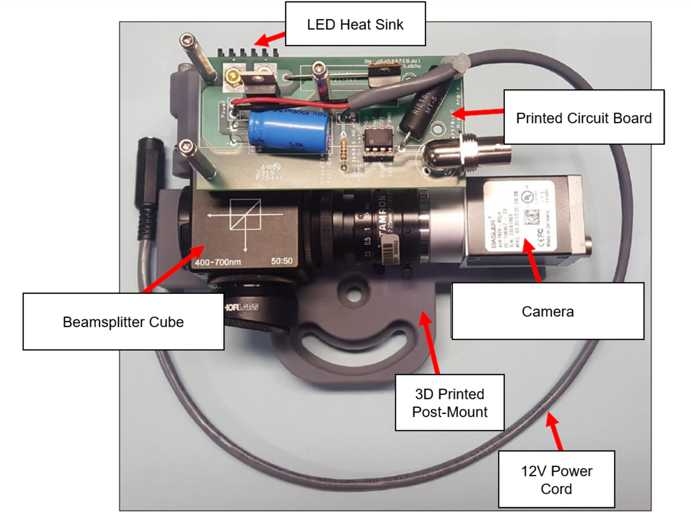
NASA’s imaging system is comprised of a small CMOS camera fitted with a C-mount lens affixed to a 3D-printed mount. Light from the high-intensity LED is passed through a lens that both diffuses and collimates the LED output, and this light is coupled onto the cameras optical axis using a 50:50 beam-splitting prism.
Use of the collimating/diffusing lens to condition the LED output provides for an illumination source that is of similar diameter to the camera’s imaging lens. This is the feature that reduces or eliminates shadows that would otherwise be projected onto the subject plane as a result of refractive index variations in the imaged volume. By coupling the light from the LED unit onto the camera’s optical axis, reflections from windows – which are often present in wind tunnel facilities to allow for direct views of a test section – can be minimized or eliminated when the camera is placed at a small angle of incidence relative to the window’s surface. This effect is demonstrated in the image on the bottom left of the page.
Eight imaging systems were fabricated and used for capturing background oriented schlieren (BOS) measurements of flow from a heat gun in the 11-by-11-foot test section of the NASA Ames Unitary Plan Wind Tunnel (see test setup on right). Two additional camera systems (not pictured) captured photogrammetry measurements.

