Search
Optics
3D Lidar for Improved Rover Traversal and Imagery
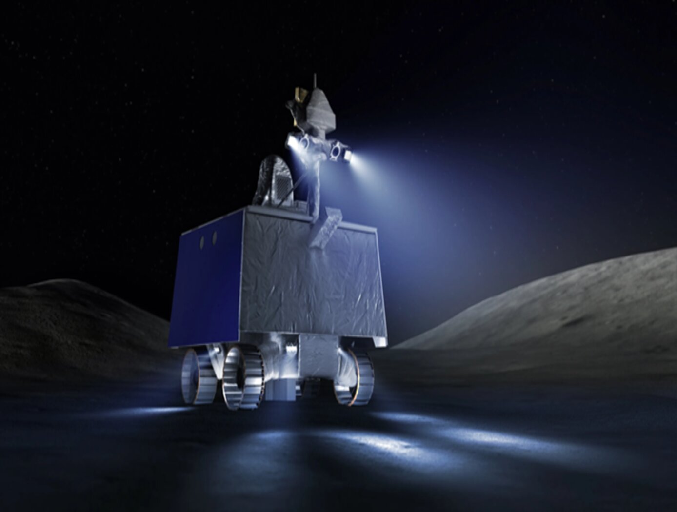
The SQRLi system is made up of three major components including the laser assembly, the mirror assembly, and the electronics and data processing equipment (electronics assembly) as shown in the figure below. The three main systems work together to send and receive the lidar signal then translate it into a 3D image for navigation and imaging purposes.
The rover sensing instrument makes use of a unique fiber optic laser assembly with high, adjustable output that increases the dynamic range (i.e., contrast) of the lidar system. The commercially available mirror setup used in the SQRLi is small, reliable, and has a wide aperture that improves the field-of-view of the lidar while maintaining a small instrument footprint. Lastly, the data processing is done by an in-house designed processor capable of translating the light signal into a high-resolution (sub-millimeter) 3D map. These components of the SQRLi enable successful hazard detection and navigation in visibility-impaired environments.
The SQRLi is applicable to planetary and lunar exploration by unmanned or crewed vehicles and may be adapted for in-space servicing, assembly, and manufacturing purposes. Beyond NASA missions, the new 3D lidar may be used for vehicular navigation in the automotive, defense, or commercial space sectors. The SQRLi is available for patent licensing.
power generation and storage
Optimum Solar Conversion Cell Configurations
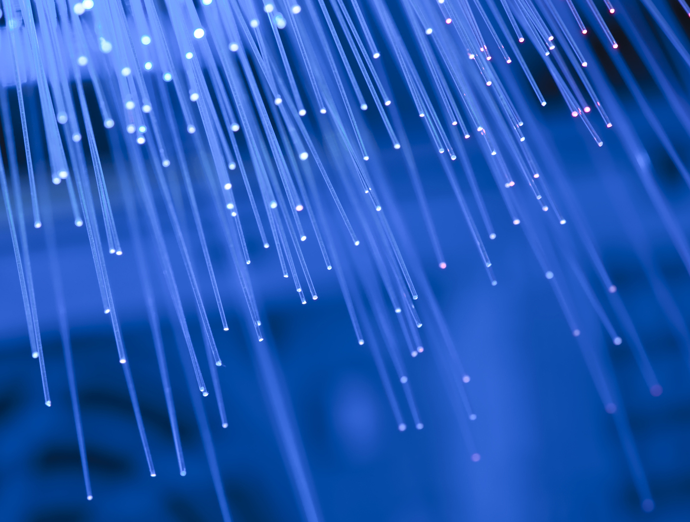
A solar cell manufactured from this new optical fiber has photovoltaic (PV) material integrated into the fiber to enable electricity generation from unused light, including non-visible portions of the spectrum and visible light not transmitted to a lighting application. These new solar cells are based around cylindrical optical fibers, providing two distinct advantages over the flat panels that lead to increased efficiency. The core fiber, used to transmit light, can be adjusted to increase or decrease the amount of available light that is transmitted to the lighting application at any point in real time. This invention can be applied wherever optical concentrators are used to collect and redirect incident light. Wavelengths as large as 780 nanometers (nm) can be used to drive the conversion process. This technology has very low operating costs and environmental impacts (in particular, no greenhouse gas emissions). The fiber uses low-cost polymer materials. It is lightweight and flexible, and can be manufactured using low-cost solution processing techniques. Such multifunctional materials have great potential for the future of solar and photovoltaic devices. They will enable new devices that are small and lightweight that can be used without connection to existing electrical grids.
Sensors
Optical concentration sensor for liquid solution
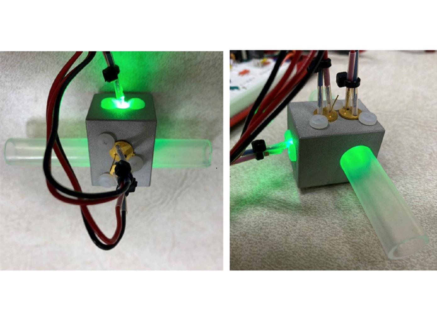
Typical concentration sensors, like the one initially used in the UWMS, rely on changes in electrical conductivity to measure the concentration of a solution. These measurements using conductivity are prone to voltage drift over time, leading to unreliable measurements as the sensor ages.
The optical sensor developed here uses light scattering to measure the solution concentration without the issue of voltage drift. In this sensor, light from a green LED is passed into the sensor housing where it hits a first detector (i.e., a photodiode) to establish a reference of the amount of light before scattering. Simultaneously, the light from the LED scatters through the pretreat solution and then hits a second photodiode to measure the amount of light after scattering. The difference between the amount of light measured by the two detectors is used to calculate the concentration of the pretreat solution (based upon Beer’s Law). The optical concentration sensor has been demonstrated to effectively measure pretreat concentrations in both still and flowing liquid conditions and is resistant to contamination issues as necessitated by the UWMS.
The optical pretreat concentration sensor is at technology readiness level (TRL) 4 (component and/or breadboard validation in laboratory environment) and is available for patent licensing.
sensors
Lightweight Fiber Optic Sensors for Real-Time Monitoring of Structural Health
<strong><i>How It Works </strong></i>
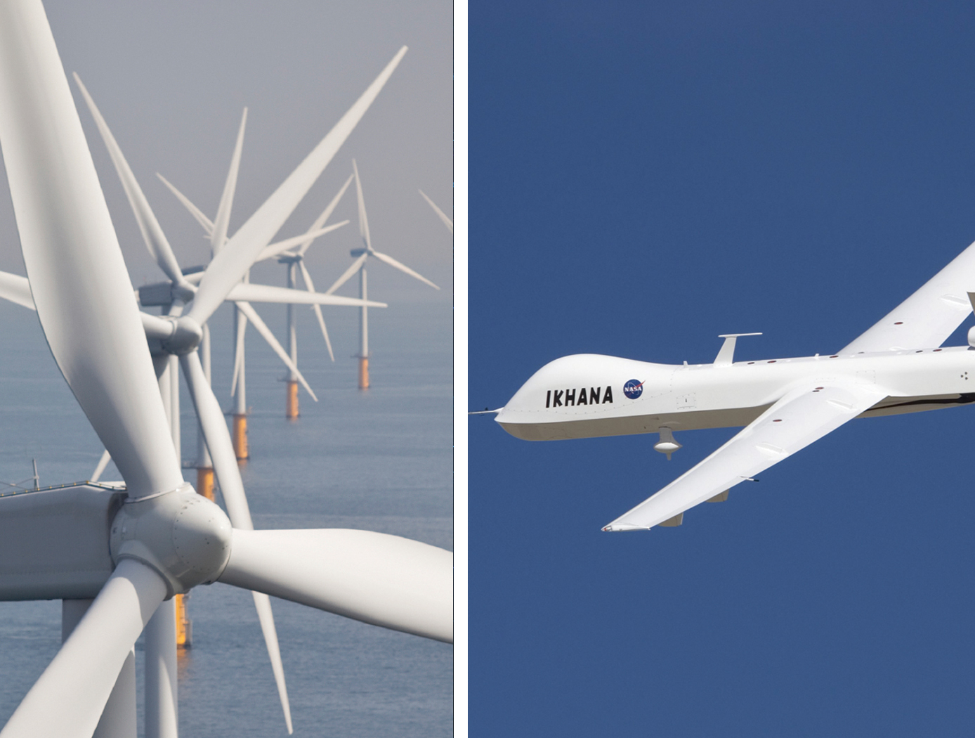
The FOSS technology employs efficient, real-time, data driven algorithms for interpreting strain data. The fiber Bragg grating sensors respond to strain due to stress or pressure on the substrate. The sensors feed these strain measurements into the systems algorithms to determine shape, stress, temperature, pressure, strength, and operational load in real time.
<strong><i>Why It Is Better </strong></i>
Conventional strain gauges are heavy, bulky, spaced at distant intervals (which leads to lower resolution imaging), and unable to provide real-time measurements. Armstrong's system is virtually weightless, and thousands of sensors can be placed at quarter-inch intervals along an optical fiber the size of a human hair. Because these sensors can be placed at such close intervals and in previously inaccessible regions (for example, within bolted joints, embedded in a composite structure), the high-resolution strain measurements are more precise than ever before. The fiber optic sensors are non-intrusive and easy to install—thousands of sensors can be installed in less time than conventional strain sensors and the system is capable of processing information at the unprecedented rate of 100 samples per second. This critical, real-time monitoring capability enables an immediate and informed response in the event of an emergency and allows for precise, controlled monitoring to help avoid such scenarios.
<b><i>For more information about the full portfolio of FOSS technologies, see DRC-TOPS-37 or visit <a href=https://technology-afrc.ndc.nasa.gov/featurestory/fiber-optic-sensing>https://technology-afrc.ndc.nasa.gov/featurestory/fiber-optic-sensing</a></b></i>
instrumentation
Assembly for Simplified Hi-Res Flow Visualization
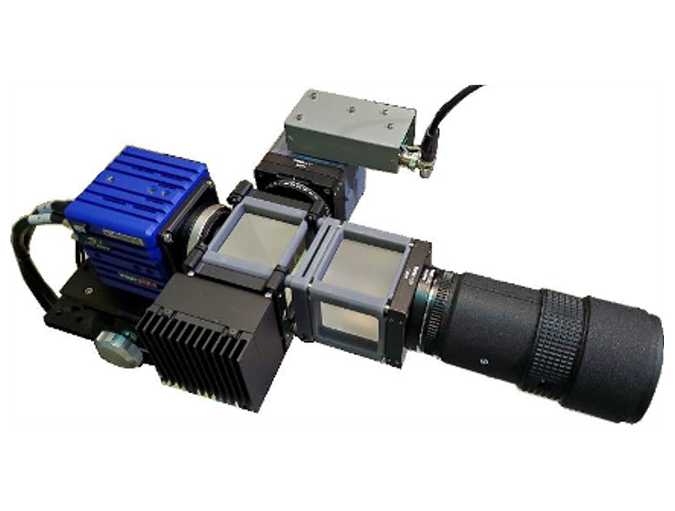
NASAs single grid, self-aligned focusing schlieren optical assembly is attached to a commercial-off-the-shelf camera. It directs light from the light source through a condenser lens and linear polarizer towards a polarizing beam-splitter where the linear, vertically-polarized component of light is reflected onto the optical axis of the instrument. The light passes through a Ronchi ruling grid, a polarizing prism, and a quarter-wave plate prior to projection from the assembly as right-circularly polarized light. The grid-patterned light (having passed through the Ronchi grid) is directed past the density object onto a retroreflective background that serves as the source grid. Upon reflection off the retroreflective background, the polarization state of light is mirrored. It passes the density object a second time and is then reimaged by the system. Upon encountering the polarizing prism the second time, the light is refracted resulting in a slight offset. This refracted light passes through the Ronchi ruling grid, now serving as the cutoff grid, for a second time before being imaged by the camera.
Both small- and large-scale experimental set ups have been evaluated and shown to be capable of fields-of-view of 10 and 300 millimeters respectively. Observed depths of field were found to be comparable to existing systems. Light sources, polarizing prisms, retroreflective materials and lenses can be customized to suit a particular experiment. For example, with a high speed camera and laser light source, the system has collected flow images at a rate of 1MHz.
sensors
Sensing Magnetic Fields
This technology is part of Armstrong's portfolio of fiber optic sensing technologies known as FOSS. The innovation leverages Armstrong's cutting edge work in this area, including its patented FBG interrogation system, which allows for a diverse set of engineering measurements in a single compact system. In addition to magnetic field, other measurements include structural shape and buckling modes, external loads, and cryogenic liquid level. The system and measurement technology is commercially available for research applications. In addition to capitalizing on the significant advancements in fiber optic and laser technologies that have been made to support the telecommunications industry, Armstrong has also partnered with UCLA's Active Materials Lab (AML) to tap their expertise in the field of magnetics.
<b><i>For more information about the full portfolio of FOSS technologies, see DRC-TOPS-37 or visit <a href=https://technology-afrc.ndc.nasa.gov/featurestory/fiber-optic-sensing>https://technology-afrc.ndc.nasa.gov/featurestory/fiber-optic-sensing</a></b></i>
Optics

Filtered Ronchi Rulings for Enhanced Schlieren Imaging
The first optic is a 1D Ronchi ruling, where shortpass or longpass filters replace the traditional opaque lines in the grid pattern. The second optic is a 2D Ronchi ruling, where one set of lines is made from shortpass filters and the orthogonal set from longpass filters. By using two colors of light and a color camera in the focusing schlieren system (or a dichroic mirror with two monochrome cameras), the 1D optic enables simultaneous focusing schlieren and other co-linear techniques, while the 2D optic allows for the unambiguous measurement of two orthogonal density gradients in focusing schlieren images.
Unlike standard optical filters, which typically cover an entire substrate, these Ronchi rulings feature alternating clear and filtered regions in structured 1D or 2D patterns. By leveraging color filtering and a color camera, the 1D ruling enables simultaneous focusing schlieren and complementary optical diagnostics, such as Particle Image Velocimetry (PIV), Pressure-Sensitive Paint (PSP), and Thermal-Sensitive Paint (TSP). The 2D ruling enables simultaneous and unambiguous measurement of two orthogonal density gradients, a capability not possible with conventional Ronchi rulings. This advancement significantly improves the accuracy and efficiency of schlieren-based flow measurements. The types of filters are not just limited to shortpass and longpass coatings, but could include notch, bandpass, and multiple-bandpass filter coatings as well.
This design expands the utility of schlieren imaging in high-speed aerodynamics, combustion diagnostics, and other fluid dynamics applications. This Ronchi ruling methodology is at TRL 4 (component and/or breadboard validation in a lab environment) and is available for patent licensing.
Sensors

Receiver for Long-distance, Low-backscatter LiDAR
The NASA receiver is specifically designed for use in coherent LiDAR systems that leverage high-energy (i.e., > 1mJ) fiber laser transmitters. Within the receiver, an outgoing laser pulse from the high-energy laser transmitter is precisely manipulated using robust dielectric and coated optics including mirrors, waveplates, a beamsplitter, and a beam expander. These components appropriately condition and direct the high-energy light out of the instrument to the atmosphere for measurement. Lower energy atmospheric backscatter that returns to the system is captured, manipulated, and directed using several of the previously noted high-energy compatible bulk optics. The beam splitter redirects the return signal to mirrors and a waveplate ahead of a mode-matching component that couples the signal to a fiber optic cable that is routed to a 50/50 coupler photodetector. The receiver’s hybrid optic design capitalizes on the advantages of both high-energy bulk optics and fiber optics, resulting in order-of-magnitude enhancement in performance, enhanced functionality, and increased flexibility that make it ideal for long-distance or low-backscatter LiDAR applications.
The related patent is now available to license. Please note that NASA does not manufacturer products itself for commercial sale.
Instrumentation

Digital Projection Focusing Schlieren System
NASA’s digital projection focusing Schlieren system is attached to a commercial-off-the-shelf camera. For focusing Schlieren measurements, it directs light from the light source through a condenser lens and linear polarizer towards a beam-splitter where linear, vertically-polarized component of light is reflected onto the optical axis of the instrument. The light passes through the patterned LCD element, a polarizing prism, and a quarter-wave plate prior to projection from the assembly as left- or right-circularly polarized light. The grid-patterned light (having passed through the LCD element) is directed past the density object onto a retroreflective background (RBG) that serves as the source grid. Upon reflection off the RBG, the polarization state of light is mirrored. It passes the density object a second time and is then reimaged by the system. Upon encountering the polarizing prism the second time, the light is slightly offset. This refracted light passes through the LCD element, now serving as the cutoff grid, for a second time before being imaged by the camera.
The LCD element can be programmed to display a variety of grid patterns to enable sensitivity to different density gradients. The color properties of the LCD can be leveraged in combination with multiple colored light sources to enable simultaneous multi-color, multi-technique data collection.
This system is ready for integration into commercial flow visualization and diagnostic equipment, offering manufacturers and research facilities an efficient, cost-effective solution for multi-technique imaging. The Schlieren system is currently available for patent licensing.
sensors

Streamlined Liquid Level Sensing Using Fiber Optics
Armstrong has developed a robust fiber optic–based sensing technology that offers extraordinary accuracy in liquid level measurements. The sensing system uses fiber optic Bragg sensors located along a single fiber optic cable. These sensors actively discern between the liquid and gas states along a continuous fiber and can accurately pinpoint the liquid level.
<strong><i>How It Works</strong></i>
The technology uses a resistive heater wire bundled with the optical fiber. The heater is pulsed to induce a local temperature change along the fiber, and the fiber Bragg grating data is used to monitor the subsequent cooling of the fiber. The length of fiber in the liquid cools more rapidly than the portion of the fiber in the gas above the liquid. The measurement system accurately establishes the location of this transition to within 1/4-inch.
<strong><i>Why It Is Better</strong></i>
Armstrong's liquid level sensing technology was originally developed to measure cryogenic liquid levels in rockets, and it represents a significant advancement in the state of the art in this application. Conventional methods for measuring cryogenic liquid levels rely on cryogenic diodes strategically placed along a rod or rack. The diodes are mounted in pre-selected, relatively widely spaced positions along the length of a rod; this configuration provides limited, imprecise data. Furthermore, each diode on the rod has two wires associated with it, which means a single system may require a large number of wires, making installation, connectivity, and instrumentation cumbersome.
Armstrong's novel technology provides liquid measurements with much greater precision, achieving measurements at 1/4-inch intervals. Furthermore, the streamlined system uses just two wires, which greatly simplifies installation and instrumentation. Due to its extraordinary accuracy and ease of use, Armstrong's measurement system offers important advantages for a wide range of applications beyond cryogenic liquids.
<strong><i>In Addition</strong></i>
Researchers have developed a new manufacturing process that improves the ability of fiber optic sensing systems to measure temperature and liquid levels when operating in humid environments. The process involves eliminating moisture from the optical fiber coating, then completing the sensor assembly within humidity-controlled conditions. The resulting sensor hardware provides precise and accurate measurements even when operating in a humid environment.
<b><i>For more information about the full portfolio of FOSS technologies, see DRC-TOPS-37 or visit <a href=https://technology-afrc.ndc.nasa.gov/featurestory/fiber-optic-sensing>https://technology-afrc.ndc.nasa.gov/featurestory/fiber-optic-sensing</a></b></i>

