Search
Propulsion
Small Spacecraft Electric Propulsion (SSEP) Technology Suite
Innovators at GRC have developed a suite of SSEP technologies for small, low-power spacecraft using Hall effect thrusters including a high propellant throughput small spacecraft electric propulsion thruster (LEW-TOPS-158), a power processing unit for SSEP (LEW-TOPS-157), an anode manifold plug for Hall effect thrusters (LEW-TOPS-159), and additional Hall effect technologies (LEW-TOPS-34). See the <i>Additional Information</i> section at the bottom of the page for more information on each technology suite component.
GRC is making these technologies available to U.S. companies through a no-cost*, non-exclusive license agreement and companion Space Act Agreement. Licensees may receive a comprehensive package of design and process documents including issued and pending patents, design drawings, materials specifications, and test data. Licensees will assist in defining system requirements and creating new platforms to use the SSEP technologies. This streamlined, collaborative commercialization strategy helps satisfy NASA exploration and science mission requirements while improving U.S. competitiveness in the global electric propulsion market and improving the success of new electric propulsion developments. Working alongside our licensees, GRC hopes to generate a compendium of SSEP knowledge as a living document, maintained by all users in a consortia-like environment.
*Although the license and Space Act Agreement are no cost to the licensees, licensees would be responsible for setting up and maintaining an EAR restricted file sharing space.
Manufacturing
Additively Manufactured Propulsion Catalysts
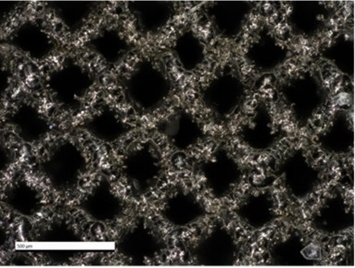
Working with EOS, a market leader in additive manufacturing (AM) technology, NASA has pioneered the use of AM to achieve improved performance and cost reduction of propulsion catalyst systems. As mentioned above, conventional mono-propulsion catalysts are comprised of ceramic or graphite foams, which possess thousands of irregular pores with non-uniform size and distribution. Due to the lack of granular control in the manufacturing process, such foams are limited in terms of feasible designs. These foams also exhibit anisotropic mechanical properties and inconsistent fluid flow behavior. Furthermore, such catalysts are produced by a limited number of vendors, constraining availability and inflating cost. As with several other aerospace structures, AM of mono-propulsion catalysts enables increased manufacturing capabilities (e.g., granular geometric control, repeatability) while reducing cost and lead time.
NASA and EOS leveraged AM to generate ultra-fine lattice structures – repeating unit cells with ligament thickness as small as 100 microns – to replace coated ceramic or graphite foam catalysts. These AM lattice structures offer several advantages including increased control of structure topology, unconstrained designed flexibility, improved compressive strength, and fluid flow optimization – all printed into a single component from a preferred refractory platinum metal. Granular control of structure topology allows for tailored percent relative density (%RD), which in turn allows manufacturers to control the mechanical and fluid flow properties of the final catalyst structure. In other words, NASA’s AM ultra-fine lattice catalyst structures significantly improve upon the drawbacks of conventional catalysts by offering a higher degree of control over the structure, enabling the generation of catalysts with customized material properties. In addition, the use of AM ensures the catalysts exhibit high spatial symmetry and can be generated in a repeatable (non-stochastic) manner, all while reducing cost and lead times.
While NASA and EOS' ultra-fine lattice structures were originally developed for mono-propellant systems (e.g., green propellant thruster catalysts), the same structures and manufacturing technologies can be applied to liquid or gas permeable rigid materials, evaporative film cooling heat exchangers, filtering, and other applications.
robotics automation and control
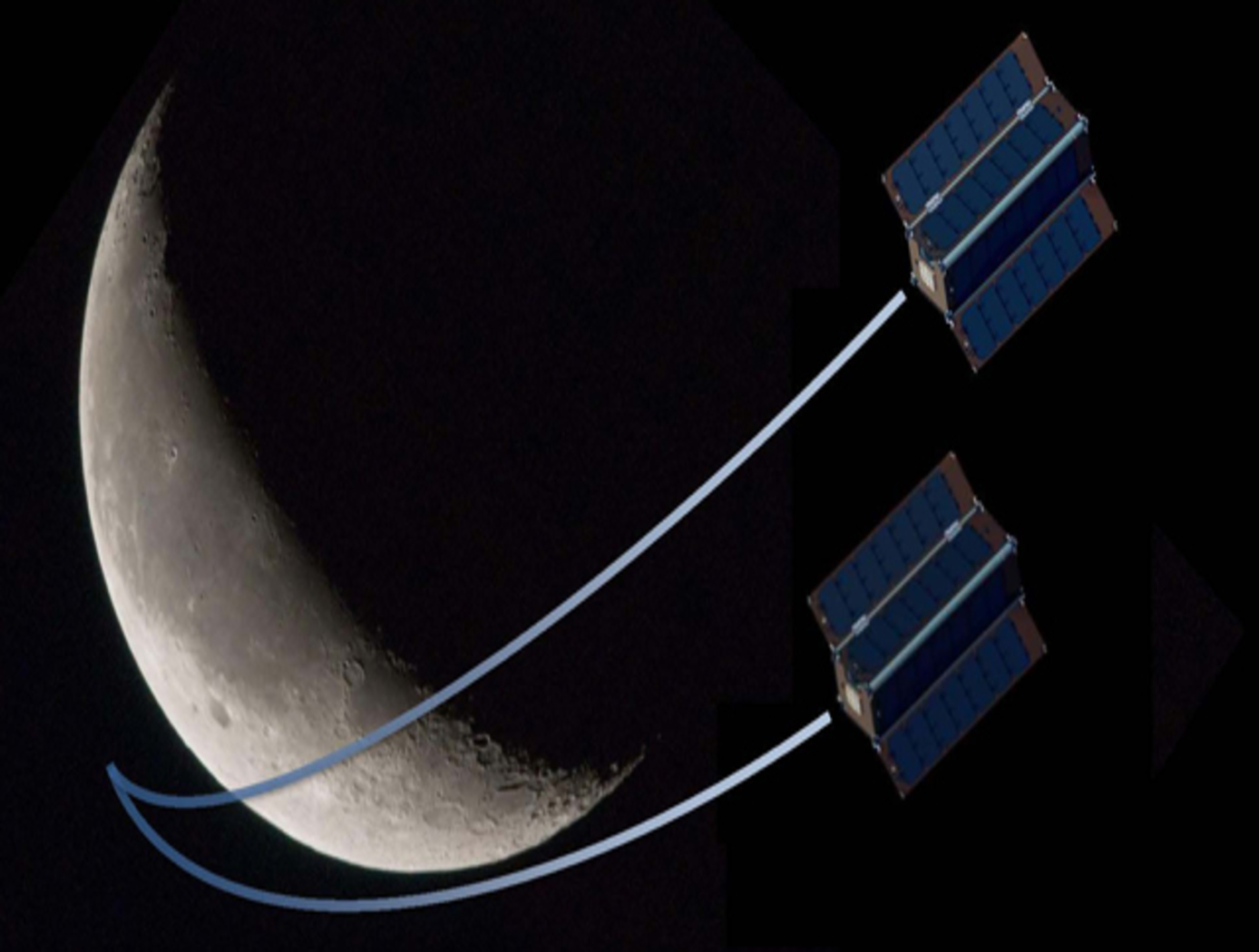
Gimbal for Steering Propelled CubeSats
The small thruster mount, roughly the size of a doughnut, controls the rotation and tilt of a directional system to a high degree of accuracy (0.02 degrees). NASA developed the rotary tilting gimbal (RTG) for thruster directional control of CubeSats. This RTG is designed to provide precision control in both the tilting and rotary degree of freedom by using accurate positioning, encoded piezoelectric motors, and a close tolerance machined structure. The RTG functions via rotary motion of the integrated assembly by a grounded piezoelectric support motor, and tilts via a rotary motor that rides on the primary structure. This alleviates the need for more traditional, directional control hardware, including magnetorquers and magnetometers. The subject technology has a resulting rotational degree of freedom of 360 degrees and a tilting degree of freedom of +/- 12 degrees. The rotary motor is connected to the tilt plate by a two-piece crank assembly. The gimbal weight, including the motors, is about 420 grams; without motors, it is about 100 grams. The operating temperature range is 0-50C. Sinusoidal testing was performed before and after the random vibration tests to determine if any structural changes occurred as a result of the tests. The gimbal met the qualification requirements and did not present any significant structural changes from flight-level testing.
Mechanical and Fluid Systems
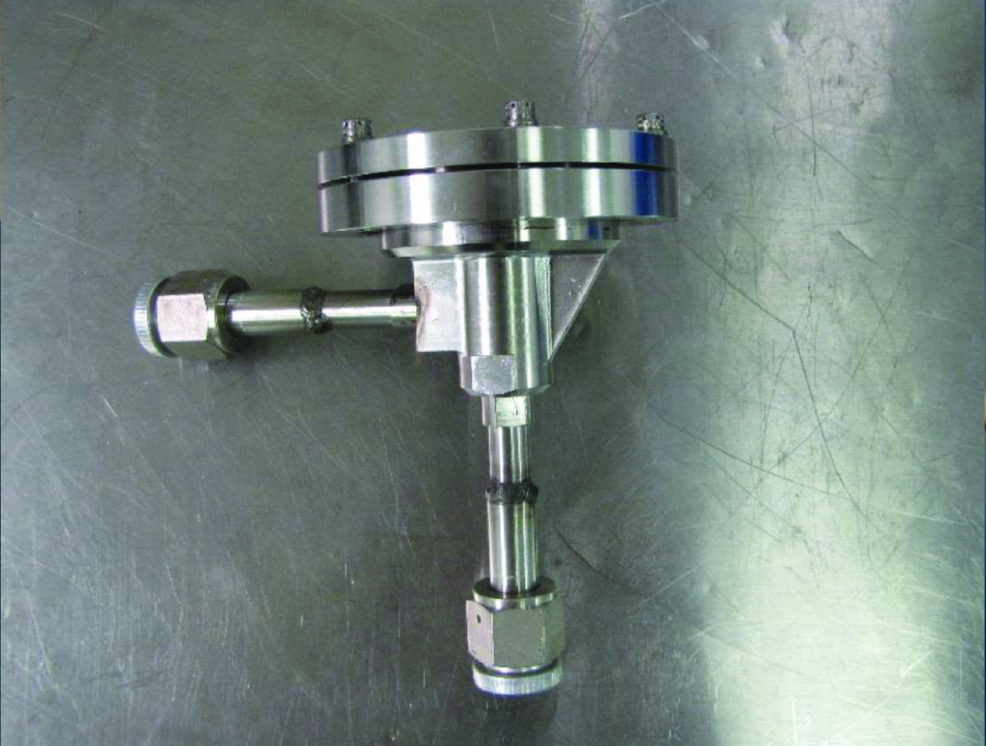
Pilot Assisted Check Valve for Low Pressure Applications
Check valves are traditionally designed as a simple poppet/spring system where the spring is designed to equal the force created from the sealing area of the valve seat multiplied by the cracking pressure. Since the valve seat diameter in these types of valves are relatively small, less than 0.5 inches diameter, a low cracking pressure required for back pressure relief devices results in a low spring preload. When sealing in the reverse direction, the typical 20 psid storage pressure of the cryogenic fluid is not enough pressure force to provide adequate sealing stress. To better control the cracking pressure and sealing force, a bellows mechanism was added to a poppet check valve (see Figure 2). The bellows serves as a reference pressure gauge; once the targeted pressure differential is reached, the bellows compresses and snaps the valve open. Prior to reaching the desired crack pressure differential, the bellows diaphragm is fully expanded, providing sufficient seal forces to prevent valve flow (including reverse flow) and undesired internal leakage. Room temperature testing of cracking pressure, full flow pressure, and flow capacity all showed improvements. The overall results of the test proved to be 10-20 times greater than conventional check valves with no internal leakage at three different pressure differentials.
Mechanical and Fluid Systems

Magnetically Damped Check Valve
The oscillatory behavior can lead to seal wear, increased leakage, and the generation of foreign object debris (FOD), which is particularly problematic in high-reliability systems like spacecraft or cryogenic propulsion. The valve integrates a magnetic damping system into a conventional check valve architecture. Key components include a non-magnetic, electrically conductive poppet body (e.g., copper), a ferromagnetic sleeve (e.g., HIPERCO 50A) inside the poppet, and a set of Neodymium Iron Boron (NdFeB) magnetized rings arranged in alternating polarities around a non-magnetic valve body. A second ferromagnetic sleeve completes the magnetic circuit, concentrating magnetic flux through the poppet during motion.
When the valve operates, the poppet moves in response to pressure differentials. As it travels through the magnetic field, eddy currents are induced in the conductive poppet body. These currents generate a magnetic field that opposes the motion of the poppet, providing velocity-proportional damping based on Lenz’s Law. This passive damping mechanism prevents oscillation and chatter without relying on fluid viscosity or mechanical contact, enabling smooth, reliable valve operation across a wide range of flow conditions. The system is tuned to achieve critical damping by balancing magnetic flux, poppet mass, and spring rate.
This innovation offers significant advantages. In aerospace applications, the valve can be used in purge systems or cryogenic fluid lines to eliminate chatter, improving valve longevity and reducing FOD risk. In the oil and gas industry, it can enhance safety and reliability in high-pressure systems where valve failure could be catastrophic. Industrial processing systems benefit from reduced maintenance and improved flow stability. The valve’s passive, wear-free damping also lowers lifecycle costs and simplifies design integration, making it attractive for commercial licensing and deployment across multiple sectors. This technology is TRL 3 and is currently available for licensing.
power generation and storage
High Efficiency Megawatt Motor
The HEMM is a is a wound-field partially superconducting machine that implements a combination of rotor superconducting and stator normal conductor elements, along with an integrated acoustic cryocooler, to achieve some of the benefits of a superconducting motor without the need for an external cryogenic system. The combination of the described elements allows a motor to be built which essentially operates like any other motor when viewed as a black box, but substantially enhanced performance can be achieved. The incorporation of superconductors on the rotor to create a high-level magnetic field results in a specific power and efficiency that could not be achieved any other way. The HEMM can achieve over 98% efficiency in a lightweight electric machine with an operating power greater than 1.4 MW, a specific power greater than 16 kW/kg (ratio to electromagnetic mass), and a rated operating speed of 6800 RPM. The HEMM can be used as both a motor or a generator, offering a wide range of applications including propulsion systems for hybrid aircraft, electric trains, hybrid cars, and turboelectric ships, as well as generator systems for wind turbines, power plants, or motors for other industrial machinery.
Mechanical and Fluid Systems
Miniature Separable Fill & Drain Valve
The Miniature Separable Fill & Drain Valve consists of two halves (ground and flight). The flight half is attached to the vehicle (i.e., CubeSat), and the ground half can be inserted into the vehicle in the same port as the flight half, connecting the two halves together. In normal state, the flight half seals the flow path. When the ground half is connected, the flow path is opened, allowing connected ground support equipment to supply fluid through the valve. The valve is manually operated.
There are redundant seals to eliminate leakage around the valve, including NASA's previously-patented Low-Cost, Long Lasting Valve Seal design (Patent No. 10,197,165; see MFS-TOPS-71 in the <i>Links</i> section of this flyer for more information) on the flight half. This eliminates the need for a swaged assembly process and the additional hardware and equipment that are typically required in conventional, elastomeric valve seat installations. The design also includes a cap for the flight half to ensure there is no leakage in flight configuration.
The Miniature Separable Fill & Drain Valve has been prototyped and provides valuable benefits for CubeSat applications. The valve could also have applications in the industrial processing industry where low flow devices are commonly used. The design is also scalable to larger applications where the removal of the actuation device would be desired.
propulsion

Power Processing Unit (PPU) for Small Spacecraft Electric Propulsion
Key subsystems of a scalable PPU for low-power Hall effect electric propulsion have been developed and demonstrated at NASA GRC. The PPU conditions and supplies power to the thruster and propellant flow control (PFC) components. It operates from an input voltage of 24 to 34 VDC to be compatible with typical small spacecraft with 28 V unregulated power systems. The PPU provides fault protection to protect the PPU, thruster, PFC components, and spacecraft. It is scalable to accommodate various power and operational requirements of low-power Hall effect thrusters. An important subsystem of a PPU is the discharge supply, which processes up to 95% of the power in the PPU and must process high voltage to accelerate thrust generating plasma. Each discharge power module in this PPU design is capable of processing up to 500 W of power and output up to 400 VDC. A full-bridge topology operating at switching frequency 50 kHz is used with a lightweight foil transformer. Two or more modules can operate in parallel to scale up the discharge power as required. Output voltage and current regulation controls allow for any of the common thruster start-up modes (hard, soft or glow).
<br><br><br>
propulsion
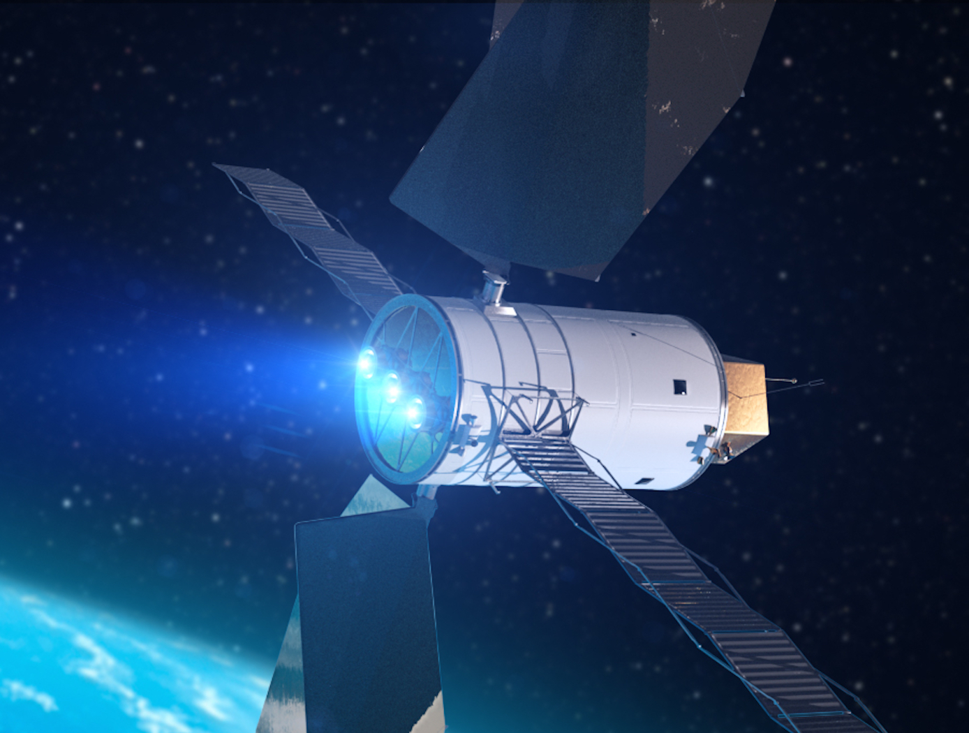
Sublimable Propellant Source for Iodine-fed Ion Propulsion System
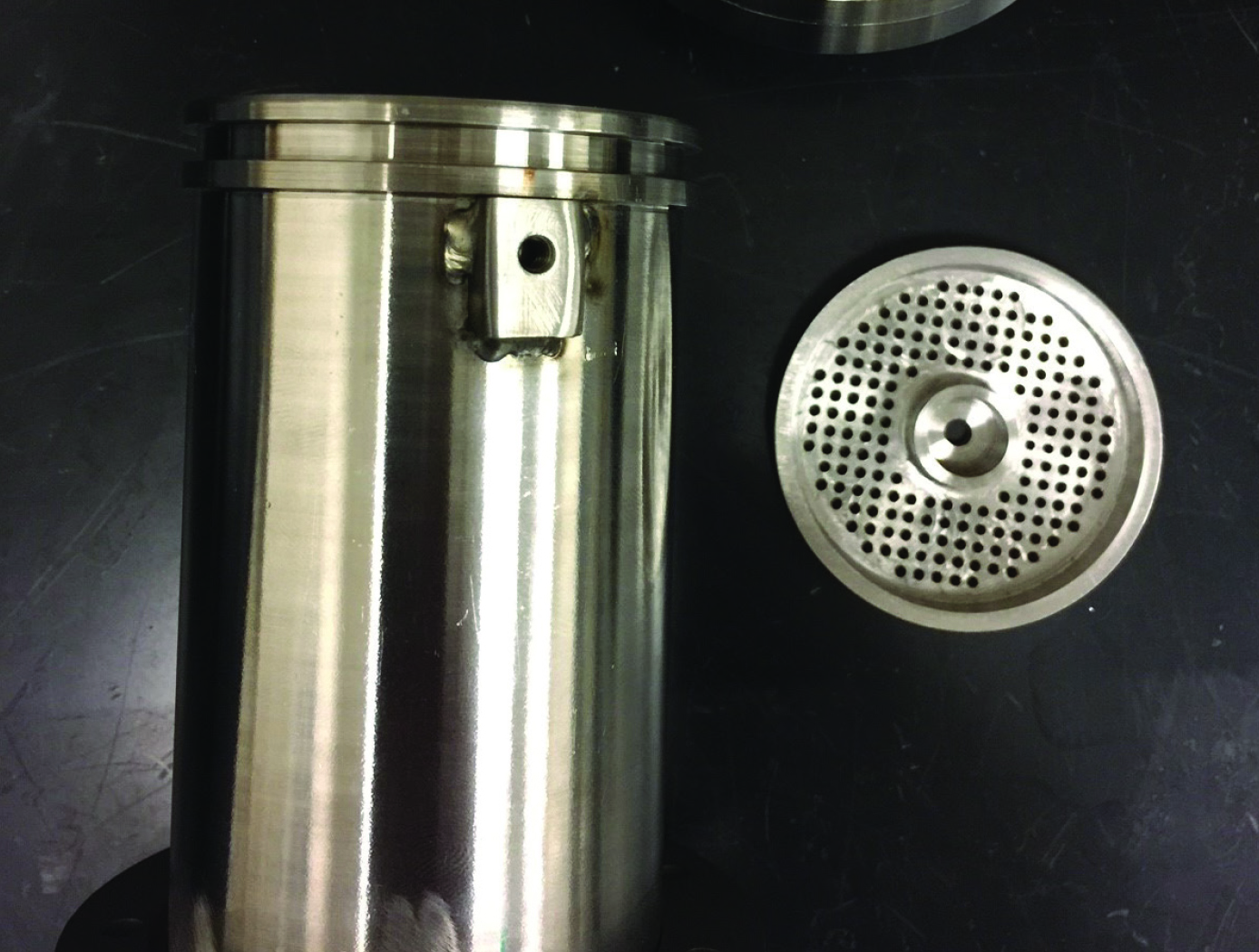
NASAs iodine vapor feed system is based on a mechanism that holds and maintains the solid iodine is contact with a heated surface, in this case the walls of the propellant tank. The mechanism provides a robust and reliable steady-state delivery of sublimated iodine vapor to the ion propulsion system by ensuring good thermal contact between the solid iodine and the tank walls.
To date, the technology development effort includes extensive thermal, mechanical and flow modelling together with testing of components and subsystems required to feed iodine propellant to a 200-W Hall thruster. The feed system has been designed to use materials that are resistant to the highly-reactive nature of iodine propellant. Dynamic modeling indicates that the feed system tubing can be built is such a way as to reduce vibrationally-induced stresses that occur during launch. Thermal modeling has been performed to demonstrate that the feed system heater power levels are sufficient to heat the tank and propellant lines to operating temperatures, and sublime the iodine in the storage tank to supply propellant for reliable and long-term operation.
Propulsion

Improving Hybrid Electric Propulsion Efficiency
Electrically driven turbine engine compressor and propulsion fans require a large stability margin against stall conditions to avoid unwanted performance issues while undergoing transients in operating conditions. This stability margin, while it maintains safe operation, also necessarily reduces the engine performance. Despite extensive research efforts, no viable alternative methods for reducing the operable stability margin and improving engine performance exist. This current innovation, originally conceived for stall prevention, offers a solution by utilizing a supercapacitor in line with an electric motor and motor controller to rapidly change a compressor or propulsor fan speed. The use of the supercapacitor enables rapid extraction, or addition of power, to prevent the fan from stalling.
Additionally, this novel drive motor may be used for sensing stall event precursor signals by using the motor controller to detect variations in torque on the shaft caused by variance in loading on the blade system. The improved stall avoidance capabilities allow an engine fan to operate more efficiently, providing more thrust for a given frontal area, increasing operational range, reduced weight, and improved operational safety.
The related patent is now available to license. Please note that NASA does not manufacture products itself for commercial sale.

