Search
Manufacturing
Additively Manufactured Propulsion Catalysts
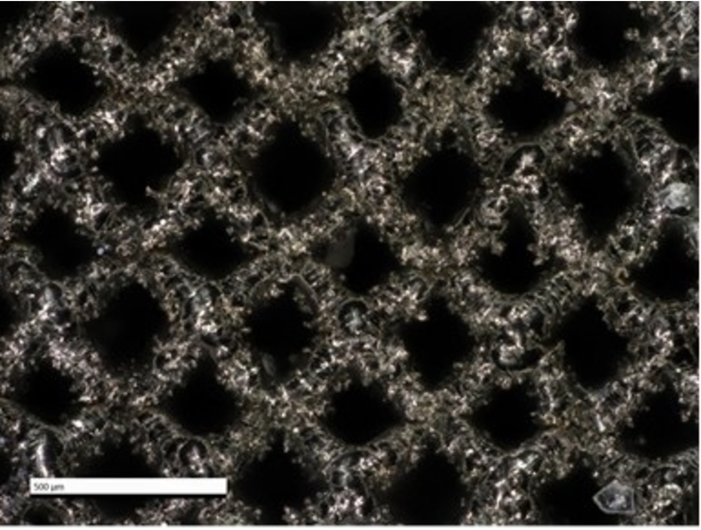
Working with EOS, a market leader in additive manufacturing (AM) technology, NASA has pioneered the use of AM to achieve improved performance and cost reduction of propulsion catalyst systems. As mentioned above, conventional mono-propulsion catalysts are comprised of ceramic or graphite foams, which possess thousands of irregular pores with non-uniform size and distribution. Due to the lack of granular control in the manufacturing process, such foams are limited in terms of feasible designs. These foams also exhibit anisotropic mechanical properties and inconsistent fluid flow behavior. Furthermore, such catalysts are produced by a limited number of vendors, constraining availability and inflating cost. As with several other aerospace structures, AM of mono-propulsion catalysts enables increased manufacturing capabilities (e.g., granular geometric control, repeatability) while reducing cost and lead time.
NASA and EOS leveraged AM to generate ultra-fine lattice structures – repeating unit cells with ligament thickness as small as 100 microns – to replace coated ceramic or graphite foam catalysts. These AM lattice structures offer several advantages including increased control of structure topology, unconstrained designed flexibility, improved compressive strength, and fluid flow optimization – all printed into a single component from a preferred refractory platinum metal. Granular control of structure topology allows for tailored percent relative density (%RD), which in turn allows manufacturers to control the mechanical and fluid flow properties of the final catalyst structure. In other words, NASA’s AM ultra-fine lattice catalyst structures significantly improve upon the drawbacks of conventional catalysts by offering a higher degree of control over the structure, enabling the generation of catalysts with customized material properties. In addition, the use of AM ensures the catalysts exhibit high spatial symmetry and can be generated in a repeatable (non-stochastic) manner, all while reducing cost and lead times.
While NASA and EOS' ultra-fine lattice structures were originally developed for mono-propellant systems (e.g., green propellant thruster catalysts), the same structures and manufacturing technologies can be applied to liquid or gas permeable rigid materials, evaporative film cooling heat exchangers, filtering, and other applications.
propulsion

Power Processing Unit (PPU) for Small Spacecraft Electric Propulsion
Key subsystems of a scalable PPU for low-power Hall effect electric propulsion have been developed and demonstrated at NASA GRC. The PPU conditions and supplies power to the thruster and propellant flow control (PFC) components. It operates from an input voltage of 24 to 34 VDC to be compatible with typical small spacecraft with 28 V unregulated power systems. The PPU provides fault protection to protect the PPU, thruster, PFC components, and spacecraft. It is scalable to accommodate various power and operational requirements of low-power Hall effect thrusters. An important subsystem of a PPU is the discharge supply, which processes up to 95% of the power in the PPU and must process high voltage to accelerate thrust generating plasma. Each discharge power module in this PPU design is capable of processing up to 500 W of power and output up to 400 VDC. A full-bridge topology operating at switching frequency 50 kHz is used with a lightweight foil transformer. Two or more modules can operate in parallel to scale up the discharge power as required. Output voltage and current regulation controls allow for any of the common thruster start-up modes (hard, soft or glow).
<br><br><br>
propulsion
Sublimable Propellant Source for Iodine-fed Ion Propulsion System
NASAs iodine vapor feed system is based on a mechanism that holds and maintains the solid iodine is contact with a heated surface, in this case the walls of the propellant tank. The mechanism provides a robust and reliable steady-state delivery of sublimated iodine vapor to the ion propulsion system by ensuring good thermal contact between the solid iodine and the tank walls.
To date, the technology development effort includes extensive thermal, mechanical and flow modelling together with testing of components and subsystems required to feed iodine propellant to a 200-W Hall thruster. The feed system has been designed to use materials that are resistant to the highly-reactive nature of iodine propellant. Dynamic modeling indicates that the feed system tubing can be built is such a way as to reduce vibrationally-induced stresses that occur during launch. Thermal modeling has been performed to demonstrate that the feed system heater power levels are sufficient to heat the tank and propellant lines to operating temperatures, and sublime the iodine in the storage tank to supply propellant for reliable and long-term operation.
Propulsion
Anode Manifold Plug for Hall Effect Thrusters
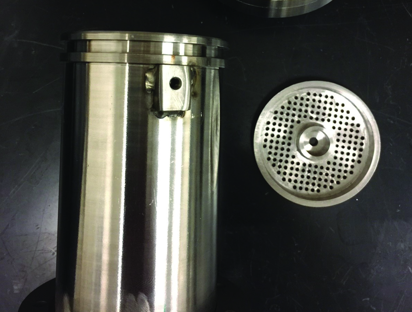
Flow-restricting features in a Hall thruster anode manifold assembly, typically precision manufactured orifices, can contribute to significant flow non-uniformity if tolerances on the features are not properly controlled. Non-uniformity in flow distribution negatively impacts thruster performance. The anode assembly is usually a complex and expensive assembly to manufacture. Removing the flow restricting elements from the anode manifold structure in favor of modular insertable subcomponents (i.e., plugs) enables the use of more reliable and repeatable precision manufacturing techniques. The resulting components can be tested, characterized, and sorted for acceptance before being installed into the larger anode assembly (i.e., quality control can be performed at the subcomponent level). This may lead to increased performance and yield rate of the final assembly.
The flow restrictor plugs can be made in many different ways. The most basic flow restrictor takes the form of a precision hole machined into a cylinder, where the cylinder is then press fit into a hole drilled into the anode base. Alternate embodiments of the flow restrictor include precision machined nozzles, laminar flow elements, or sintered porous metal elements. The flow restrictor can also be made from a different material than the anode base, such as a precision ruby orifice contained in a metal carrier which is installed in a metal anode base. The plugs can be installed in a variety of ways, all of which create hermetic seals. Installation can include a press fit relying on plastic deformation or threading the plug component into the anode base. Welding on the top surface of the anode base can also be done to provide a robust hermetic seal.
propulsion

High Propellant Throughput Small Spacecraft Electric Propulsion Thruster
NASAs High Propellant Throughput Small Spacecraft Electric Propulsion thruster offers a propellant throughput capability of greater than 120 kg with a nominal thruster efficiency greater than 50%. The new thruster design combines heritage Hall thruster component design approaches with recent NASA GRC advancements in the areas of advanced magnetic circuit design, robust propellant manifolds, and center mounted cathodes. Prototypes of the High Propellant Throughput Small Spacecraft Electric Propulsion thruster have been fabricated and proof-of-concept has been demonstrated.
A significant advancement in the High Propellant Throughput Small Spacecraft Electric Propulsion thruster is NASA's optimized magnetically shielded (OMS) field topology. The new OMS configuration reduces discharge channel erosion rates compared to conventional Hall thrusters, while reducing front pole cover erosion rates compared to traditional magnetically shielded Hall thrusters. This system also includes a largely unibody structure to reduce fabrication cost, increase strength, and optimize thermal management. A coupling plate between the high voltage discharge channel and low voltage thruster body allows more efficient thruster assembly and verification processes. Other design advancements further simplify assembly, improve robustness, and optimize performance.
Propulsion

Small Spacecraft Electric Propulsion (SSEP) Technology Suite
Innovators at GRC have developed a suite of SSEP technologies for small, low-power spacecraft using Hall effect thrusters including a high propellant throughput small spacecraft electric propulsion thruster (LEW-TOPS-158), a power processing unit for SSEP (LEW-TOPS-157), an anode manifold plug for Hall effect thrusters (LEW-TOPS-159), and additional Hall effect technologies (LEW-TOPS-34). See the <i>Additional Information</i> section at the bottom of the page for more information on each technology suite component.
GRC is making these technologies available to U.S. companies through a no-cost*, non-exclusive license agreement and companion Space Act Agreement. Licensees may receive a comprehensive package of design and process documents including issued and pending patents, design drawings, materials specifications, and test data. Licensees will assist in defining system requirements and creating new platforms to use the SSEP technologies. This streamlined, collaborative commercialization strategy helps satisfy NASA exploration and science mission requirements while improving U.S. competitiveness in the global electric propulsion market and improving the success of new electric propulsion developments. Working alongside our licensees, GRC hopes to generate a compendium of SSEP knowledge as a living document, maintained by all users in a consortia-like environment.
*Although the license and Space Act Agreement are no cost to the licensees, licensees would be responsible for setting up and maintaining an EAR restricted file sharing space.
Electrical and Electronics
Coil-On-Plug Igniter for Reliable Engine Starts
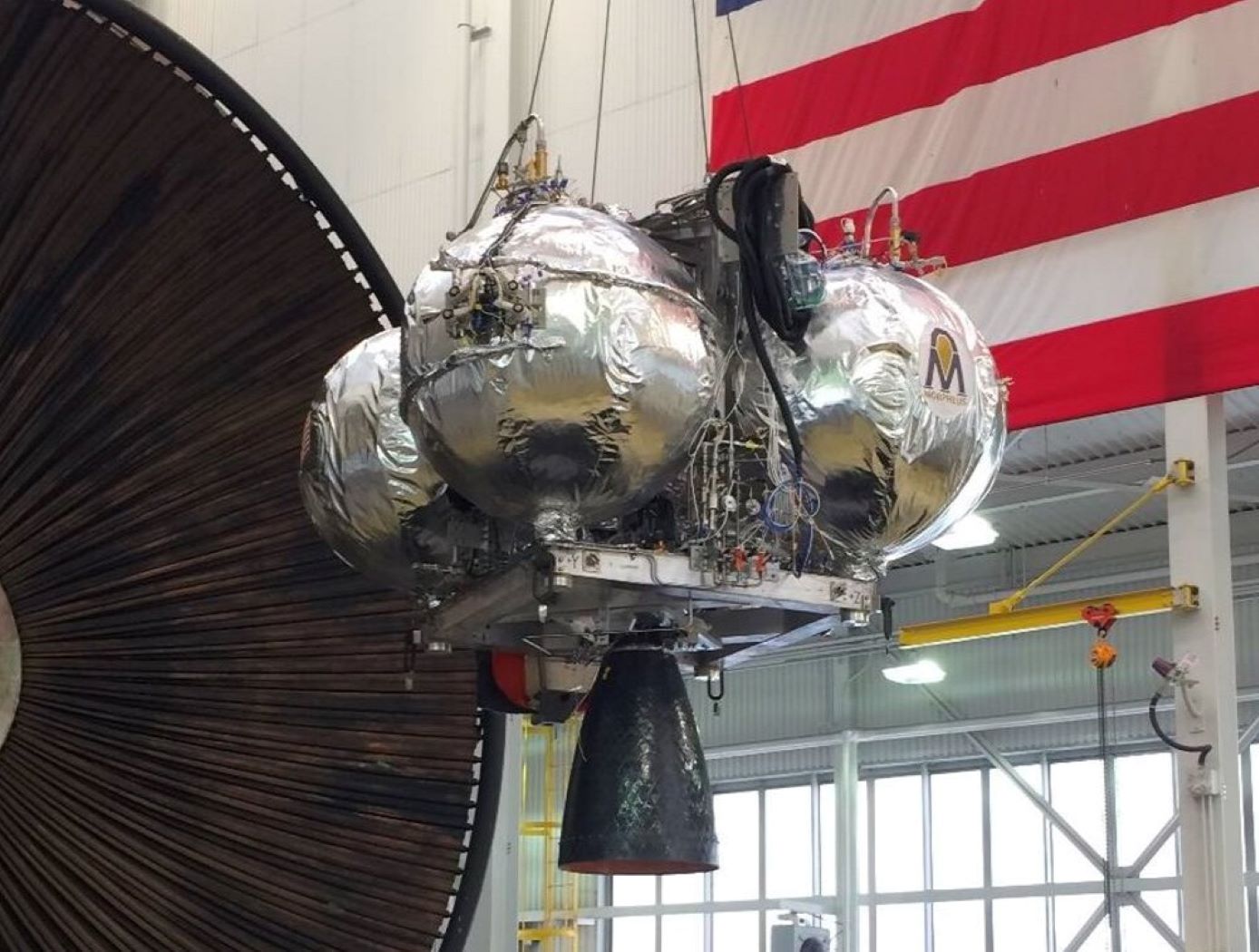
Spark-ignition devices have proven to be a high-reliability option for LOX/LCH4 ignition during development of the Integrated Cryogenic Propulsion Test Article (ICPTA) main and reaction control engines (RCEs); however, issues including spark plug durability (ceramic cracking) and corona discharge during simulated altitude testing have been observed, contributing to degraded spark output and no-light engine-start conditions. Innovators discovered that ignition system reliability could be improved and weight reduced by eliminating the traditional coil and spark plug wire. To achieve this result, engineers made the innovation by modifying an automotive coil-on-plug igniter to provide new high sparking energies at the point of combustion using low supply voltages. The coil was modified by vacuum-potting it into a threaded interface that mounts into existing spark plug ports on the ICPTA main engine and the RCEs. Engineers fabricated custom electrode tips that were thread-mounted into the potted coil body. Epoxy insulation was chosen with high dielectric strength to maintain insulation between the electrode and threaded adapter. Vacuum potting successfully prevented pressure or vacuum leakage into the coil body and maintained spark energy and location at the electrode tip. Successful hot-fire ignition was observed at sea-level, altitude, and thermal-vacuum for both ICPTA RCE and main engine igniters down to 10^-3 torr, which approaches the vacuum of cislunar space.
This technology is at technology readiness level (TRL) 7 (system prototype demonstration in an operational environment), and the related patent is now available to license. Please note that NASA does not manufacture products itself for commercial sale.
Mechanical and Fluid Systems

Low-Cost, Long-Lasting Valve Seal
NASA's technique simplifies the seat installation process by requiring less installation equipment, eliminating the need for unnecessary apparatus such as fasteners and retainers. Multiple seals can be installed simultaneously, saving both time and money.
NASA has tested the long-term performance of a solenoid actuated valve with a seat that was fitted using the new installation technique. The valve was fabricated and tested to determine high-cycle and internal leakage performance for an inductive pulsed plasma thruster (IPPT) application for in-space propulsion. The valve demonstrated the capability to throttle the gas flow rate while maintaining low leakage rates of less than
10<sup>-3</sup> standard cubic centimeters per second (sccss) of helium (He) at the beginning of the valves lifetime. The IPPT solenoid actuated valve test successfully reached 1 million cycles with desirable leakage performance, which is beyond traditional solenoid valve applications requirements. Future design iterations can further enhance the valve's life span and performance.
The seat seal installation method is most applicable to small valve instruments that have a small orifice of 0.5 inches or less.
Aerospace
Aerospace Vehicle Entry Flightpath Control
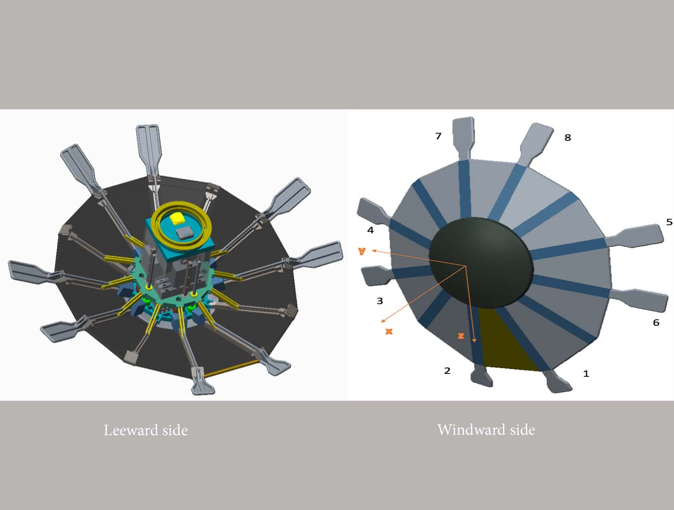
This novel flightpath control system exploits the dihedral effect to control the bank angle of the vehicle by modulating sideslip (Figure 1). Exploiting the dihedral effect, in combination with significant aerodynamic forces, enables faster bank accelerations than could be practically achieved through typical control strategies, enhancing vehicle maneuverability. This approach enables vehicle designs with fewer control actuators since roll-specific actuators are not required to regulate bank angle. The proposed control method has been studied with three actuator systems (figure below), Flaps Control System (FCS); Mass Movement Control System (MMCS); and Reaction Control System (RCS).
• FCS consists of a flap configuration with longitudinal flaps for independent pitch control, and lateral flaps generating yaw moments. The flaps are mounted to the shoulder of the vehicle’s deployable rib structure. Additionally, the flaps are commanded and controlled to rotate into or out of the flow. This creates changes in the vehicle’s aerodynamics to maneuver the vehicle without the use of thrusters.
• MMCS consists of moveable masses that are mounted to several ribs of the DEV heatshield, steering the vehicle by shifting the vehicle’s Center of Mass (CoM). Shifting the vehicle’s CoM adjusts the moment arms of the forces on the vehicle and changes the pitch and yaw moments to control the vehicle’s flightpath.
• RCS thrusters are mounted to four ribs of the open-back DEV heatshield structure to provide efficient bank angle control of the vehicle by changing the vehicle’s roll. Combining rib-mounted RCS thrusters with a Deployable Entry Vehicle (DEV) is expected to provide greater downmass capability than a rigid capsule sized for the same launch

