Tri-Rotor Steering Wheel Yields Programmable Vehicular Control
robotics automation and control
Tri-Rotor Steering Wheel Yields Programmable Vehicular Control (MSC-TOPS-122)
Allows piloting a lunar terrain vehicle using only the hands
Overview
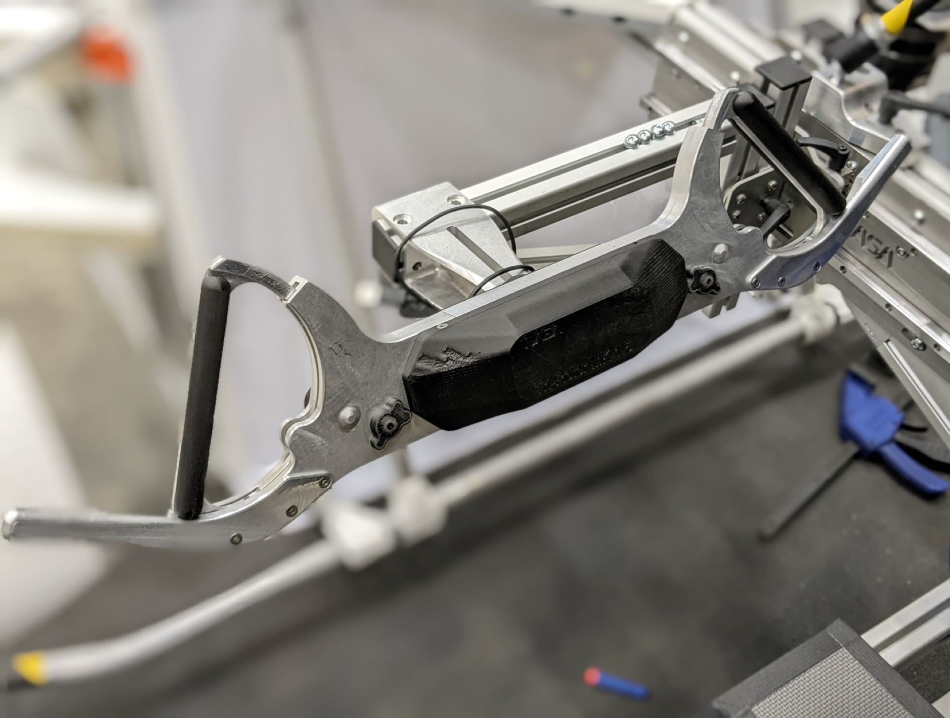
Innovators at NASA Johnson Space Center have developed a programmable steering wheel called the Tri-Rotor, which allows an astronaut the ability to easily operate a vehicle on the surface of a planet or moon despite the limited dexterity of their spacesuit.
This technology was originally conceived for the operation of a lunar terrain vehicle (LTV) to improve upon previous Apollo-era hand controllers. In re-evaluating the kinematics of the spacesuit, such as the rotatable wrist joint and the constant volume shoulder joint, engineers developed an enhanced and programmable hand controller that became the Tri-Rotor. It consists of two handles held apart by a main body whereby the handles rotate in-plane with the wrist and a central steering hub. The hub pivots in a similar fashion to an automotive steering wheel. These elements mean that an operator would only have to use their hands for directional and throttle controls. To combat fatigue during vehicular operation, the Tri-Rotor allows the astronaut to support their hands on special protrusions located on the outside of the control handles.
Due to the programmable nature of the Tri-Rotor, it may have commercial applications in any industry that utilizes a control stick, steering wheel, or yoke. The device may be especially useful in hazardous environments where operators clad in protective gear have limited dexterity.
The Technology
Since NASAs Apollo program of the late 1960s and 1970s, many previous LTV hand controllers (e.g., joysticks, T-handles) were developed and utilized albeit with shortcomings. Some of these options yielded the desired level of control but were too physically taxing to use for long periods of time in a spacesuit environment. Others simply did not offer the necessary fine motor control. Thus, there has been a long-standing need for controllers that improve upon both of these limitations.
The Tri-Rotor is a novel hand controller designed to reduce operator fatigue, add control capabilities (beyond those of a joystick), and increase the fidelity of control inputs. The design consists of two slotted handles that rotate independently within opposite sides of the Tri-Rotor main-body. Each handle is programmable and can rotate 45 degrees. In this iteration, the right handle rotates counterclockwise and acts as an accelerator and brake. The left handle rotates both clockwise and counterclockwise and controls crabbing whereby the vehicles rear wheels turn in the same direction as the front wheels facilitating diagonal or possibly lateral movement. The main-body of the Tri-Rotor rotates upon a central pivot like an automotive steering wheel and can provide directional input for Ackermann-like steering.
The handles on the Tri-Rotor are designed with spacesuit kinematics in mind and are operated using the pronated and supinated motions of the astronauts hands allowed by the wrist bearings between the glove and the forearm of the spacesuit. The devices central steering pivot is also operated by the hands and is leveraged by the up and down motions of the arms allowed by the constant volume joints in the spacesuits shoulders. This hand controller design staves off operator fatigue and sheds the need for separate fine-dexterity controls without sacrificing precision.
The Tri-Rotor Hand Controller has a technology readiness level (TRL) 5 (component and/or breadboard validation in relevant environment) and is now available for patent licensing. Please note that NASA does not manufacture products itself for commercial sale.

Benefits
- Features hands-only operation of a vehicle
- Offers fine motor control for precision operation
- Fully programmable
- Can be constructed from multiple materials
- Manufacturable
- Can be operated in conditions with limited dexterity
- Features hand supports to combat fatigue while operating vehicle
Applications
- Aerospace
- Assistive technology
- Automotive
- Demolition
- Hazardous materials
- Manufacturing
- Maritime
- Military
- Mining and construction
- Robotics
Technology Details
robotics automation and control
MSC-TOPS-122
MSC-27385-1
|
Tags:
|
Similar Results

Space Suit RoboGlove (SSRG)
NASA is currently developing the next generation space suit for future missions, including the optimization of space suit gloves. When non-assisted space suit gloves are coupled to a pressurized suit and operated in a vacuum, they tend to limit the range of motion of an astronaut's hand to as little as 20% of normal range. Many of NASA's future missions will be in challenging environments where an astronauts hand dexterity will be critical for the success of NASA missions. Innovators at JSC have improved the performance on the second-generation, robotically assisted SSRG, to reduce exertion and improve the hand strength and dexterity of an astronaut in situ.
The SSRGs system detects user finger movements using string potentiometers and contact with objects using force-sensitive resistors (FSRs). FSRs are imbedded in the distal and medial phalanges, palmar side of the glove. To move a finger, an actuator pulls a tendon through a Bowden Cable system which transfers mechanical pulling force of an inner cable relative to a hollow outer cable, like the brakes on a bicycle, as seen in the Figure below. An improved controller commands the new, more powerful linear actuator to drive tendon operation while minding custom controller parameters inputted through a digital editor tool.
The Space Suit RoboGlove is at TRL 6 (system/subsystem model or prototype demonstrated in a relevant environment) and it is now available for licensing. Please note that NASA does not manufacture products itself for commercial sale.

Foot Pedal Controller
The Foot Pedal Controller enables an operator of a spacecraft, aircraft, or watercraft, or a simulation of one in a video game, to control all translational and rotational movement using two foot pedals. This novel technology allows control across all six degrees of freedom, unlike any technology on the market. The components of the technology are a support structure, a left foot pedal, a right foot pedal, and supporting electronics. The Foot Pedal Controller is intuitive, easy to learn, and has ergonomic features that accommodate and stabilize the operator's feet. A working prototype is available to demonstrate key technology features to potential licensees.
The Foot Pedal Controller technology could be used in designs for the flight deck of the future, video game controls, drone operations and flight simulators. This technology can be useful in any application where it is preferred or desirable to use the feet to control motion rather than using the hands. A potential market could be foot control of equipment by people with arm or hand disabilities. A unique aspect of the innovation is the consideration of natural foot mechanics in the design and placement of the sensors and actuators to reduce operator fatigue. The axes of rotation of the Controller align with the joints of the foot so the foot moves naturally to control the movement of the craft. NASA seeks collaborations with companies interested in licensing and partnering to further develop and commercialize the technology.

Circumferential Scissor Spring Enhances Precision in Hand Controllers
The traditional scissor spring design for hand controllers has been improved upon with a circumferential spring controller mechanism that facilitates easy customization, enhanced durability, and optimum controller feedback. These advantages are partially facilitated by locating the spring to the outside of the mechanism which allows for easier spring replacement to adjust the deflection force or for maintenance.
The new mechanism is comprised of two rounded blades, or cams, that pivot forward and back under operation and meet to form a circle. An expansion spring is looped around the blade perimeter and resides in a channel, providing the restoring force that returns the control stick to a neutral position. Due to the use of a longer circumferential spring, the proportion of spring expansion is smaller for a given distance of deflection, so the forces associated with the deflection remain on a more linear portion of the force deflection curve.
The Circumferential Scissor Spring for Controllers is at technology readiness level (TRL) 8 (actual system completed and flight qualified through test and demonstration) and is available for patent licensing. Please note that NASA does not manufacture products itself for commercial sale.

Lunar Surface Manipulation System
NASA Langley developed the LSMS because of the need for a versatile system capable of performing multiple functions on the lunar surface, such as unloading components from a lander, transporting components to an operational site and installing them, and supporting service and replacement during component life. Current devices used for in-space operations are designed to work on orbit (zero g) only and thus do not have sufficient strength to operate on planetary surfaces. Traditional cranes are specialized to the task of lifting and are not capable of manipulator-type positioning operations.
The innovations incorporated into the LSMS allow it to lower payloads to the ground over a significant portion of the workspace without use of a hoist, functioning like a robot manipulator, thus providing a rigid connection and very precise control of the payload. The LSMS uses a truss architecture with pure compression and tension members to achieve a lightweight design. The innovation of using multiple spreaders (like spokes in a wheel) allows the LSMS to maintain its high structural efficiency throughout its full range of motion. Rod portions of the tension members automatically lift off and re-engage the spreaders as the joint articulates, allowing a large range of motion while maintaining mechanical advantage. In addition, the LSMS uses a quick-change device at the tip end that enables automated acquisition of end effectors or special purpose tools to increase its versatility.

eVTOL UAS with Lunar Lander Trajectory
This NASA-developed eVTOL UAS is a purpose-built, electric, reusable aircraft with rotor/propeller thrust only, designed to fly trajectories with high similarity to those flown by lunar landers. The vehicle has the unique capability to transition into wing borne flight to simulate the cross-range, horizontal approaches of lunar landers. During transition to wing borne flight, the initial transition favors a traditional airplane configuration with the propellers in the front and smaller surfaces in the rear, allowing the vehicle to reach high speeds. However, after achieving wing borne flight, the vehicle can transition to wing borne flight in the opposite (canard) direction. During this mode of operation, the vehicle is controllable, and the propellers can be powered or unpowered.
This NASA invention also has the capability to decelerate rapidly during the descent phase (also to simulate lunar lander trajectories). Such rapid deceleration will be required to reduce vehicle velocity in order to turn propellers back on without stalling the blades or catching the propeller vortex. The UAS also has the option of using variable pitch blades which can contribute to the overall controllability of the aircraft and reduce the likelihood of stalling the blades during the deceleration phase.
In addition to testing EDL sensors and precision landing payloads, NASA’s innovative eVTOL UAS could be used in applications where fast, precise, and stealthy delivery of payloads to specific ground locations is required, including military applications. This concept of operations could entail deploying the UAS from a larger aircraft.

