Search
PATENT PORTFOLIO
Aerospace
NASA has a wide range of advanced aerospace technologies that can be useful for both small companies seeking to introduce new solutions and large corporations looking to improve their capabilities. These technologies have the potential to transform the aerospace industry and drive the development of innovative solutions.
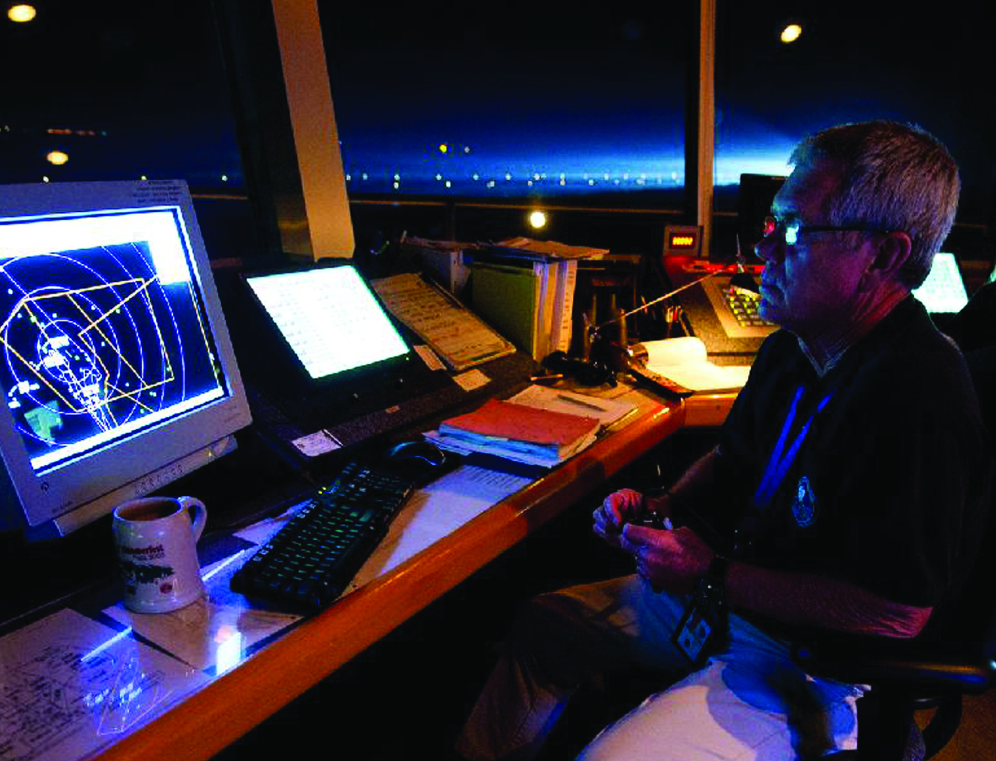
FACET: Future Air Traffic Management Concepts Evaluation Tool
Actual air traffic data and weather information are utilized to evaluate an aircrafts flight-plan route and predict its trajectories for the climb, cruise, and descent phases. The dynamics for heading (the direction the aircraft nose is pointing) and airspeed are also modeled by the FACET software, while performance parameters, such as climb/descent rates and speeds and cruise speeds, can also be obtained from data tables. The resulting trajectories and traffic flow data are presented in a 3-D graphical user interface. The FACET software is modular and is written in the Java and C programming languages. Notable FACET applications include reroute conformance monitoring algorithms that have been implemented in one of the Federal Aviation Administrations nationally deployed, real-time operational systems.
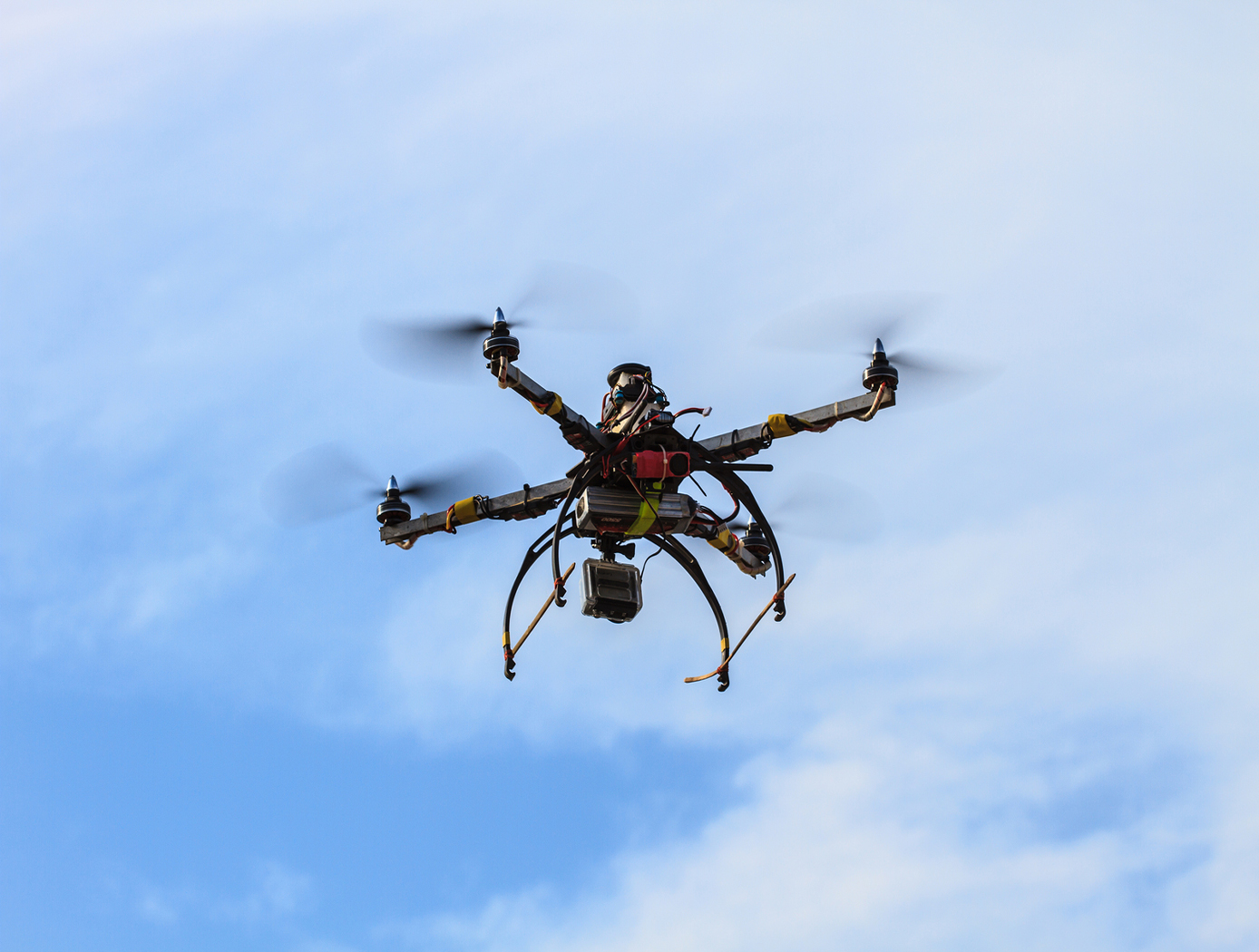
Unmanned Aerial Systems (UAS) Traffic Management
NASA Ames has developed an Autonomous Situational Awareness Platform system for a UAS (ASAP-U), a traffic management system to incorporate Unmanned Aerial Systems (UASs) into the National Airspace System. The Autonomous Situational Awareness Platform (ASAP) is a system that combines existing navigation technology (both aviation and maritime) with new procedures to safely integrate Unmanned Aerial Systems (UASs) with other airspace vehicles. It uses a module called ASAP-U, which includes a transmitter, receivers, and various links to other UAS systems. The module collects global positioning system GPS coordinates and time from a satellite antenna, and this data is fed to the UAS's flight management system for navigation. The ASAP-U module autonomously and continuously sends UAS information via a radio frequency (RF) antenna using Self-Organized Time Division Multiple Access (SOTDMA) to prevent signal overlap. It also receives ASAP data from other aircraft. In case of transmission overload, priority is given to closer aircraft. Additionally, the module can receive weather data, navigational aid data, terrain data, and updates to the UAS flight plan. The collected data is relayed to the flight management system, which includes various databases and a navigation computer to calculate necessary flight plan modifications based on regulations, right-of-way rules, terrain, and geofencing. Conflicts are checked against databases, and if none are found, the flight plan is implemented. If conflicts arise, modifications can be made. The ASAP-U module continuously receives and transmits data, including UAS data and data from other aircraft, to detect conflicts with other aircraft, terrain, weather, and geofencing. Based on this information, the flight management system determines the need for course adjustments and the flight control system executes them for a safe flight route.
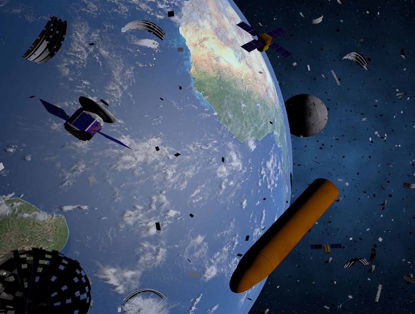
Spacecraft to Remove Orbital Debris
An approach to mitigating the creation of additional orbital debris is to remove the sources of future medium debris by actively removing large spent objects from congested orbits. NASA has introduced the ADRV, an efficient and effective solution to remove large debris from LEO such as spent rocket bodies and non-functional satellites. The concept yields a single use, low-cost, lightweight, high mass fraction vehicle that enables the specific removal of large orbital debris (1000 - 4000 kg mass, 200 - 2000 km altitude, and 20 – 98-degree inclination). The ADRV performs rendezvous, approach, and capture of non-cooperative tumbling debris objects, maneuvering of the mated vehicle, and controlled, targeted reposition or deorbit of the mated vehicle. Due to its small form factor, up to eight ADRVs can be launched in a single payload, enabling high impact orbital debris removal missions within the same inclination group.
Three key technologies were developed to enable the ADRV: - 1) The spacecraft control system (SCS) is a guidance, navigation, and control system that provides vehicle control during all phases of a mission; - (2) The debris object characterization system (DOCS) characterizes movement and capture of non-cooperative targets; and - (3) The capture and release system (CARS) allows the vehicle to capture and mate with orbital debris targets. These technologies can improve the current state-of-the-art capabilities of automated rendezvous and docking technology significantly for debris objects with tumbling rates up to 25 degrees per second. This approach leverages decades of spaceflight experience while automating key mission areas to reduce cost and improve the likelihood of success.

Vision-based Approach and Landing System (VALS)
The novel Vision-based Approach and Landing System (VALS) provides Advanced Air Mobility (AAM) aircraft with an Alternative Position, Navigation, and Timing (APNT) solution for approach and landing without relying on GPS. VALS operates on multiple images obtained by the aircraft’s video camera as the aircraft performs its descent. In this system, a feature detection technique such as Hough circles and Harris corner detection is used to detect which portions of the image may have landmark features. These image areas are compared with a stored list of known landmarks to determine which features correspond to the known landmarks. The world coordinates of the best matched image landmarks are inputted into a Coplanar Pose from Orthography and Scaling with Iterations (COPOSIT) module to estimate the camera position relative to the landmark points, which yields an estimate of the position and orientation of the aircraft. The estimated aircraft position and orientation are fed into an extended Kalman filter to further refine the estimation of aircraft position, velocity, and orientation. Thus, the aircraft’s position, velocity, and orientation are determined without the use of GPS data or signals. Future work includes feeding the vision-based navigation data into the aircraft’s flight control system to facilitate aircraft landing.
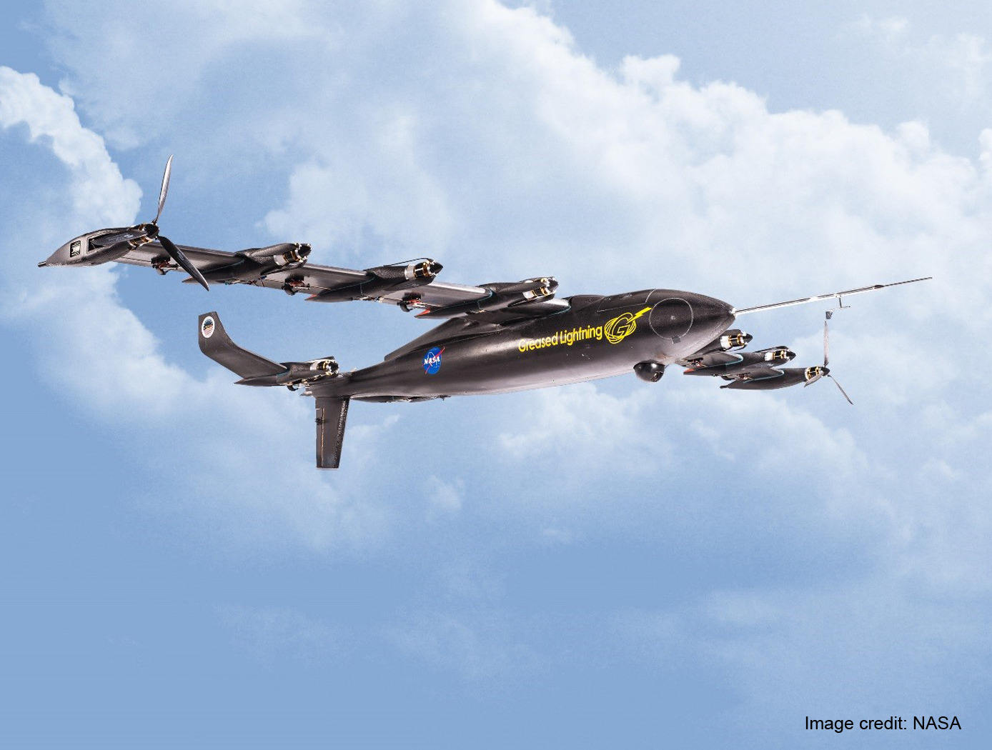
VTOL UAV With the Cruise Efficiency of a Conventional Fixed Wing UAV
The core technology that enables the Greased Lightning UAV is the aerodynamic efficiency it achieves in its cruise configuration. Electric motors at each propeller negate the need for drive shafts and gearing which enables this Distributed Electric Propulsion (DEP) aircraft configuration. The design is intended to utilize a hybrid electric drive system that includes small diesel engines which drive alternators to power the electric motors and to charge an on-board battery system. The batteries provide the power boost needed for VTOL and hovering. Numerous other novel design elements are incorporated, such as folding propellers to minimize drag when not in operation, such that the propulsive efficiency can be nearly ideal at both hover and wing borne flight conditions.

Virtual Aircraft Target Generator for ADS-B Testing
The Virtual Target Generator (VTG) is a system designed to create radio frequency (RF) signals that mimic the presence of nearby aircraft, for testing satellite-based surveillance systems. The VTG works by using a GPS receiver or other position data source to calculate a virtual target position, which may be calculated by applying predefined offsets and trajectories relative to the host. These virtual positions are encoded into standard message formats, such as ADS-B, and modulated onto an RF carrier signal.
The VTG includes a calibrated signal amplifier that adjusts the signal power so only the target test aircraft receives the signal, ensuring no other aircraft are affected. The test aircraft's surveillance avionics detect and interpret these virtual targets as if they were actual aircraft, enabling full participation in the testing of traffic collision avoidance, surveillance, or display systems.
The VTG supports complex test scenarios including dynamic movement, multiple simultaneous targets, and customizable aircraft parameters such as speed, heading, and altitude. The system is fully compliant with FAA ADS-B specifications and can be installed on the test aircraft itself or on a nearby companion aircraft.

Multistage Free-Flight Testing System
The disclosed technology provides a multistage system for evaluating the free-flight behavior of test articles across of the supersonic, transonic, and subsonic regimes. First, a drop platform is lifted to high altitudes using a lifting device, such as a stratospheric balloon. The drop platform houses multiple projectiles, each containing an ejection mechanism, an on-board avionics suit, and an instrumented test article. Upon reaching the target altitude via the lifting device, the drop platform releases the projectiles sequentially. Each projectile accelerates to a target speed and altitude before ejecting its test article into the freestream. The test articles, such as a scaled re-entry capsule, then collect flight data during their descent through the various Mach regimes, providing valuable insights into their flight performance under mission-relevant conditions.
This innovative testing system offers several benefits. It enables the simultaneous testing of multiple vehicles, facilitating the evaluation of design variations as well as statistical analyses of vehicle behavior. This system also provides significant cost savings in comparison to other state-of-the-art testing methods, such as ballistic range testing. Additionally, the test articles within each projectile are easily interchangeable through a simple, modular change of a support surface in the ejection mechanism. This flexibility enables the system to accommodate a range of other aerodynamic technologies, including other vehicles, parachutes, propulsion systems, and defense technologies. This system can enhance the efficiency and robustness of reentry vehicle design, testing, and simulation operations through the collection of rich, flight-relevant data.

Affordable Vehicle Avionics (AVA)
Significant contributors to the cost of launching nano- and micro-satellites to orbit are the costs of software, and Guidance, Navigation and Control (GNC) avionics systems that steer, navigate and control the launch vehicles, sequence stage separation, deploy payloads, and pass data to Telemetry. The high costs of these GNC avionics systems are due in part to the current practice of developing unique, custom, single-use hardware and software for each launch, and requiring high-precision measurements of position and attitude states. NASA Ames Research Center has developed and tested a low-cost avionics system prototype called Affordable Vehicle Avionics (AVA). AVA integrates a low-cost moderately-precise sensor suite with an advanced error-correcting software package to provide GNC for space launch vehicles in a package smaller than a multilayer sandwich (100 mm x 120 mm x 69 mm; 4in x 4.7in x 2.7in), and with a mass of less than 0.84kg (2lbs). The invention provides a common suite of avionics components and demonstration software that deliver affordable, capable GNC with flexible I/O which is applicable to a variety of nano/micro-sat launch vehicles at less than 10 percent of the cost to procure current state-of-the-art GNC avionics. Affordable Vehicle Avionics' (AVA's) approach to drastically reduce costs includes: (1) use of low-cost "tactical-grade" Commercial-off-the-Shelf MicroElectroMechanical Systems (MEMS) inertial measurement unit, wherein adequate navigation precision is achieved by fusing outputs from a Global Positioning System receiver, inertial sensors and a magnetic field vector sensor in an extended Kalman filter formulation that corrects inertial sensor biases; (2) a streamlined "cookbook" approach to define an effective process for launch vehicle developers to design, simulate, verify and support assembly, integration and testing of their SLVs, driven by high-fidelity six degrees of freedom SLV simulations and real-time hardware-in-loop tests to validate guidance, navigation and control for early test flights.
Development Status:
As of spring 2020, AVA has flown twice in its current configuration on a suborbital platform. Its navigation and control functions were successfully demonstrated for roll-rate control within a tight deadband onboard the first flight test, and it successfully issued attitude pointing commands to a failed reaction control subsystem and it issues issued a rocket-motor ignition command on a second flight test. To date, failure of SLV components other than AVA (e.g., electrical power) has precluded demonstration of navigation and control of an orbital or sub-orbital launch system, which remains to be demonstrated.
AVA development was accomplished using a single magnetometer-based magnetic field vector sensor to provide attitude observability during free-fall (inter-stage coast periods). Therefore, the current tested AVA configuration is susceptible to magnetic/electric fields produced by other components and payloads onboard the SLV, so care must be exercised to either mount AVA well away from sources of such fields and or to incorporate magnetic/electric field barriers on field emitters if separation from emitters is inadequate. Also, licensees may wish to provide new AVA inputs from a pair of external horizon sensors to provide more accurate attitude navigation during coast phases of the SLV mission.

Deployed Electromagnetic Radiation Deflector Shield
The typical remedy for space radiation hazards has been to harden the space vehicle's electronics and software from these high-speed particles and placing heavy shielding in these manned or sensitive areas. This adds considerable weight and cost to the launch vehicle, reduces payload capacity, and is passive in nature. SEPs and CMEs can be deflected by a magnetic field to pass around the spacecraft and not be absorbed by it. This deflection of solar wind and radiation is due to the Lorentz force. However, a magnetic field that is attached to the spacecraft and enclosing it would cause other shielding issues with equipment and would require much more electrical power to operate due to the need to enclose the entire spacecraft within that attached magnetic field.
This would also perturb the data collection and transmissions of the spacecraft. Additionally, the generated magnetic field can capture some of the solar radiation as a plasma within the magnetic torus further impeding scientific data collection due to its close position to the spacecraft.
DERDS is deployed in space away from the protected spacecraft to remain between the radiation source and the spacecraft. It utilizes on board cosmic ray sensors to note the need for the strength of the magnetic field, and on-board sensors to position itself directly in line between the radiation source and the protected spacecraft or station. Onboard computers and thrusters maintain the required position, so that the magnetic field is positioned for the best deflection angle based on incoming radiation. The DERDS magnetic field can be varied in both direction, intensity, and time by use of both AC and DC electrical power inputs and varied as needed to optimize the deflection angle and power requirements. The magnetic field can also be perturbed in irregular or set patterns by onboard computers and sensors as needed to maintain the proper deflection of SEPs, CMEs, and other cosmic rays. DERDS creates a magnetic field that will not need to be so large (with a much larger power requirement) as to encompass the entire protected spacecraft, and the magnetic field will not interfere with the spacecraft.
View more patents

